Do you have a question about the KROHNE OPTIFLEX 1100 C and is the answer not in the manual?
Guidelines for safe operation, installation, and maintenance by trained personnel.
User responsibility for suitability and intended use; supplier not liable for improper use.
Further information available in handbook and datasheet, downloadable from website.
Lists all components included with the 2mm single cable probe.
Step-by-step guide to adjust probe length and attach components for the 2mm probe.
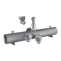
Lists all components included with the coaxial probe option.
Guide for assembling the segmented coaxial probe, including attaching tube segments.
Lists all components included with the 4mm single cable probe.
Step-by-step guide to attach the probe to the converter for the 4mm probe.
Equipment and steps for installing the device using a threaded connection.
Procedure for safely removing and re-installing the signal converter.
Instructions for opening, connecting, and closing the terminal compartment.
Reference to the handbook for detailed device configuration information.
Explanation of the default screen layout and its components.
Description of normal and configuration mode functions for keypad buttons.
Steps to set probe length, measure limits, and configure the device.
| Process Temperature | -40 to +80 °C |
|---|---|
| Protection Class / Ingress Protection | IP 66/67 |
| Application | Level measurement for liquids and solids |
| Process Pressure | Up to 4 bar |
| Output Signal | 4 ... 20 mA, HART |
| Power Supply | 12-30 V DC |
| Housing Material | Aluminium |
| Process Connection | Thread: G1½ or 1½ NPT |
| Material | PTFE |
| Certification | ATEX, IECEx |