EasyManua.ls Logo

KROHNE OPTIFLUX 5300 C User Manual

KROHNE OPTIFLUX 5300 C
47 pages
To Next Page IconTo Next Page
Page #1 background imageLoading...
Page #1 background image
GR
©
KROHNE 06/2005 7.30948.32.00
OPTIFLUX 4300 C
OPTIFLUX 5300 C
OPTIFLUX 4000 F
OPTIFLUX 5000 F
IFC 300 F
For use in hazardous areas (ATEX)
Subject to change without notice.
OPTIFLUX flowmeters are delivered ready
for operation!
Switch on and measure.
Supplement to the
QuickStart
Electromagnetic flowmeters
Variable area flowmeters
Mass flowmeters
Ultrasonic flowmeters
Vortex flowmeters
Flow controllers
Level measuring instruments
Pressure and temperature
Heat metering
Communications technology
Switches, counters, displays and recorders
Engineering systems & solutions
Question and Answer IconNeed help?

Do you have a question about the KROHNE OPTIFLUX 5300 C and is the answer not in the manual?

KROHNE OPTIFLUX 5300 C Specifications

General IconGeneral
TypeElectromagnetic Flowmeter
Nominal DiameterDN 15 to DN 1200
Temperature Range-40 to +150 °C
Electrode MaterialStainless steel, Hastelloy, Platinum, Tantalum
Lining MaterialPTFE, PFA
Housing MaterialAluminum, Stainless steel
Output Signal4-20 mA, pulse
Power Supply24 V DC
CommunicationHART, Modbus
ApprovalsATEX, IECEx
Ingress ProtectionIP67
ApplicationWater, wastewater, chemicals, food & beverage

Summary

1. Introduction

1.2 OPTIFLUX 4300

Details specific to the OPTIFLUX 4300 model, including EEx marking.

1.3 OPTIFLUX 5300

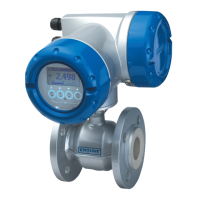
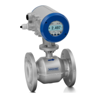
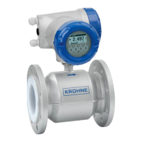
Details specific to the OPTIFLUX 5300 model, including EEx marking.

2. Temperature limits

2.1 OPTIFLUX 4300

Maximum process temperature limits for OPTIFLUX 4300 based on temperature class and ambient temperature.

2.2 OPTIFLUX 5300

Maximum process temperature limits for OPTIFLUX 5300 based on temperature class and ambient temperature.

3. Connection diagrams

4. Electrical connection

4.2 Non-EEx I signal I/O connections

Details on available non-intrinsically safe signal inputs/outputs and their functions.

4.3 EEx i signal I/O connections

Details on available intrinsically safe signal inputs/outputs and their parameters.

5. Service and maintenance

1 Description of the flowmeter

2 Electrical connection

2.2 Non-EEx i connection of signal in/outputs

2.3 EEx i connection of signal in/outputs

3 Replacement of mains fuse

4 Maintenance

Related product manuals