Do you have a question about the KROHNE OPTISONIC 6300 and is the answer not in the manual?
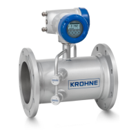
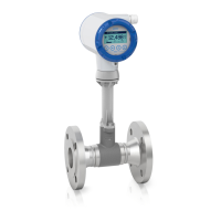
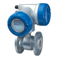
Overview of the OPTISONIC 6300 ultrasonic clamp-on flowmeter for liquid applications.
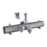
Details the different sensor rail and converter combinations available for the flowmeter.
Describes key features like sensor rail design, maintenance effort, and alignment.
Covers optional features like energy measurement and extended temperature versions.
Explains how the ultrasonic transit time principle is used for flow measurement.
General technical specifications including measuring system, design, and communication interfaces.
Provides detailed dimensions and weight information for various components.
Provides critical instructions to avoid errors and ensure safe operation during installation.
Essential safety guidelines for working with electrical connections.
Shows how to connect sensors to the signal converter for field and wall versions.
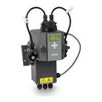
Details power supply requirements and connection methods for different voltage options.
Illustrates power supply connections for field and wall versions of the signal converter.
Instructions for connecting the sensor signal cables to the converter.
Guide for connecting modular input/output cards to the converter.
| Brand | KROHNE |
|---|---|
| Model | OPTISONIC 6300 |
| Category | Measuring Instruments |
| Language | English |