3 INSTALLATION
36
OPTISONIC 6300
www.krohne.com 09/2020 - 4006413102 - TD OPTISONIC 6300 V2 R02 en
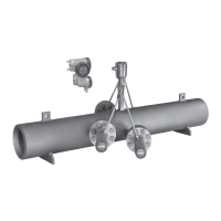
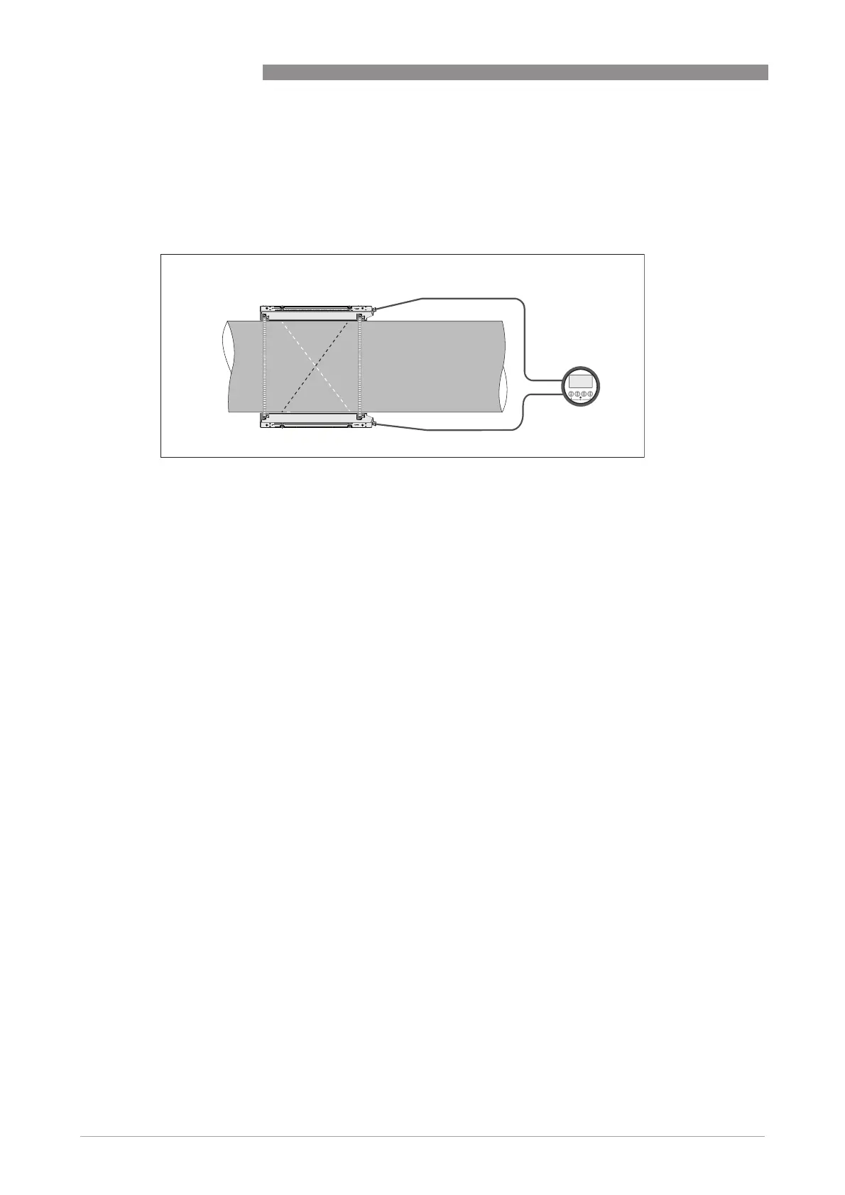
3.14 Installation instructions for X mode configuration
The X mode measurement version of the unit is setup in a 2 path configuration, with a crossed
wire connection of 2 medium sensor rails.
Install the sensor rails according to the above image. Make sure that the two rails are installed
exactly on opposite sides of the pipe.
Check the OPTISONIC 6300 manual for detailed information.
Connect the sensors according to the following instruction:
Sensor Ta
• Blue cable: U1
• Green cable: D2
Sensor Tb
• Blue cable: U2
• Green cable: D1
Set up
Programming of the sensor setup (transducer 1 settings) in the installation menu X :
• Set menu item X4.2 = number of paths o 2
• Set menu item X7.3 = number of traverses o change to 1 traverse
• Set menu item X7.4 = transducer distance o
the exact distance between up transducer of Ta to the down transducer of Tb
• Repeat the process for transducer 2
Figure 3-11: X beam configuration of medium version