4 ELECTRICAL CONNECTIONS
46
OPTISONIC 6300
www.krohne.com 09/2020 - 4006413102 - TD OPTISONIC 6300 V2 R02 en
4.4.2 Signal cable to converter
Each sensor rail has a signal cable which has to be connected, optional via a cable extension
(splitter) box, to the signal converter. The inner cables are colour-coded and labelled to apply a
correct connection of the acoustic paths.
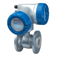
Connect the cable to the connector with similar numeral marking.
Field version
Figure 4-7: Connect signal cable
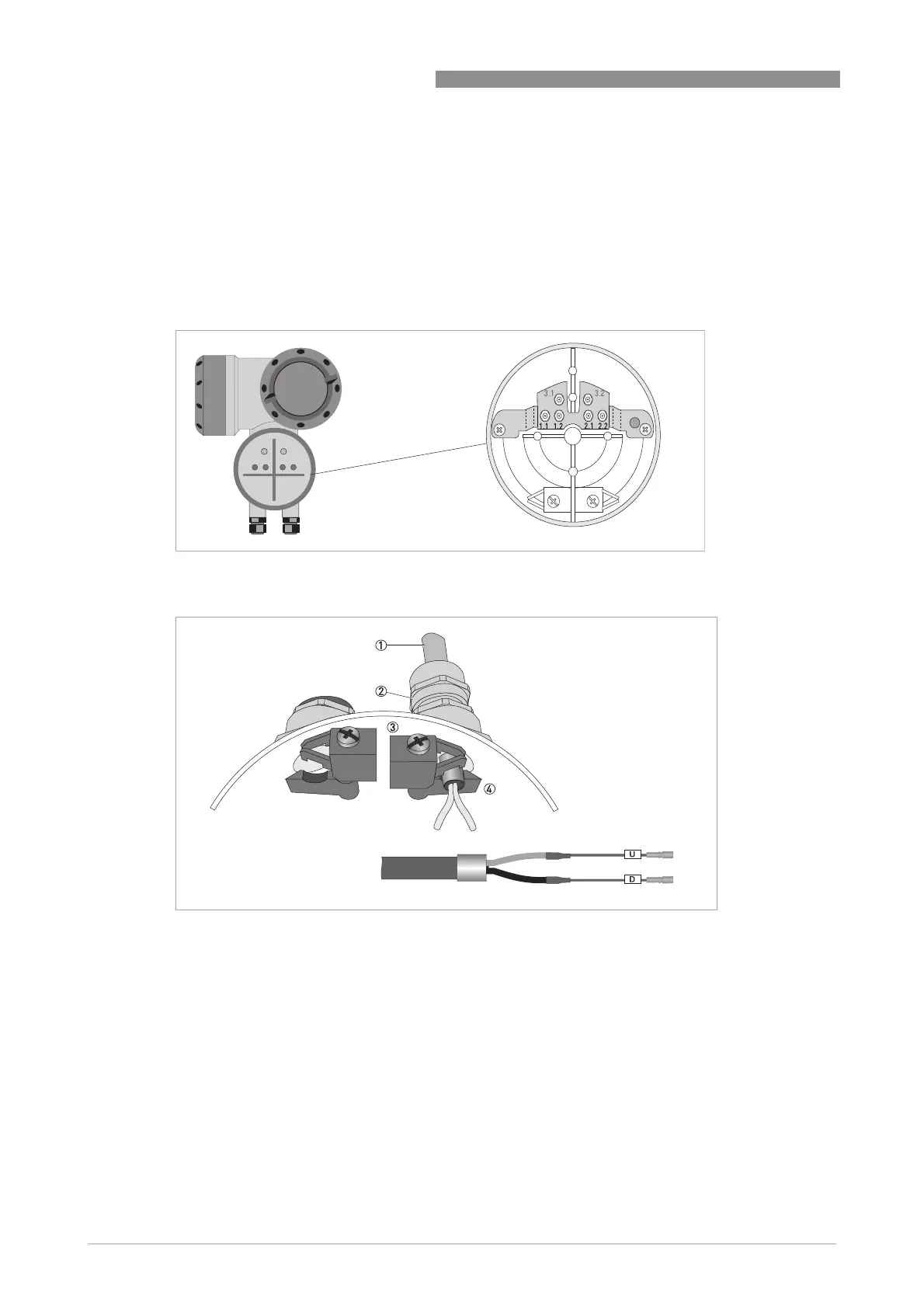
Construction of console (F-version)
Figure 4-8: Inserting cable and secure with clamp on shielding bush
1 Signal cable (blue or black)
2 Cable glands
3 Grounding clamps
4 Signal cable with metal shielding bush and wire marking
Re-connecting of the coax connectors is limited. Make sure that the male connector on the coax
cable, is always put straight on the female connector in the connection terminal of the unit.
Excessive dis- / re-connection and/or positioning the connectors skewed to each other will
damage the inside clips of the connectors. This results in an improper contact and measurement
errors.