4 ELECTRICAL CONNECTIONS
50
OPTISONIC 6300
www.krohne.com 09/2020 - 4006413102 - TD OPTISONIC 6300 V2 R02 en
4.5 Modular inputs/outputs connections
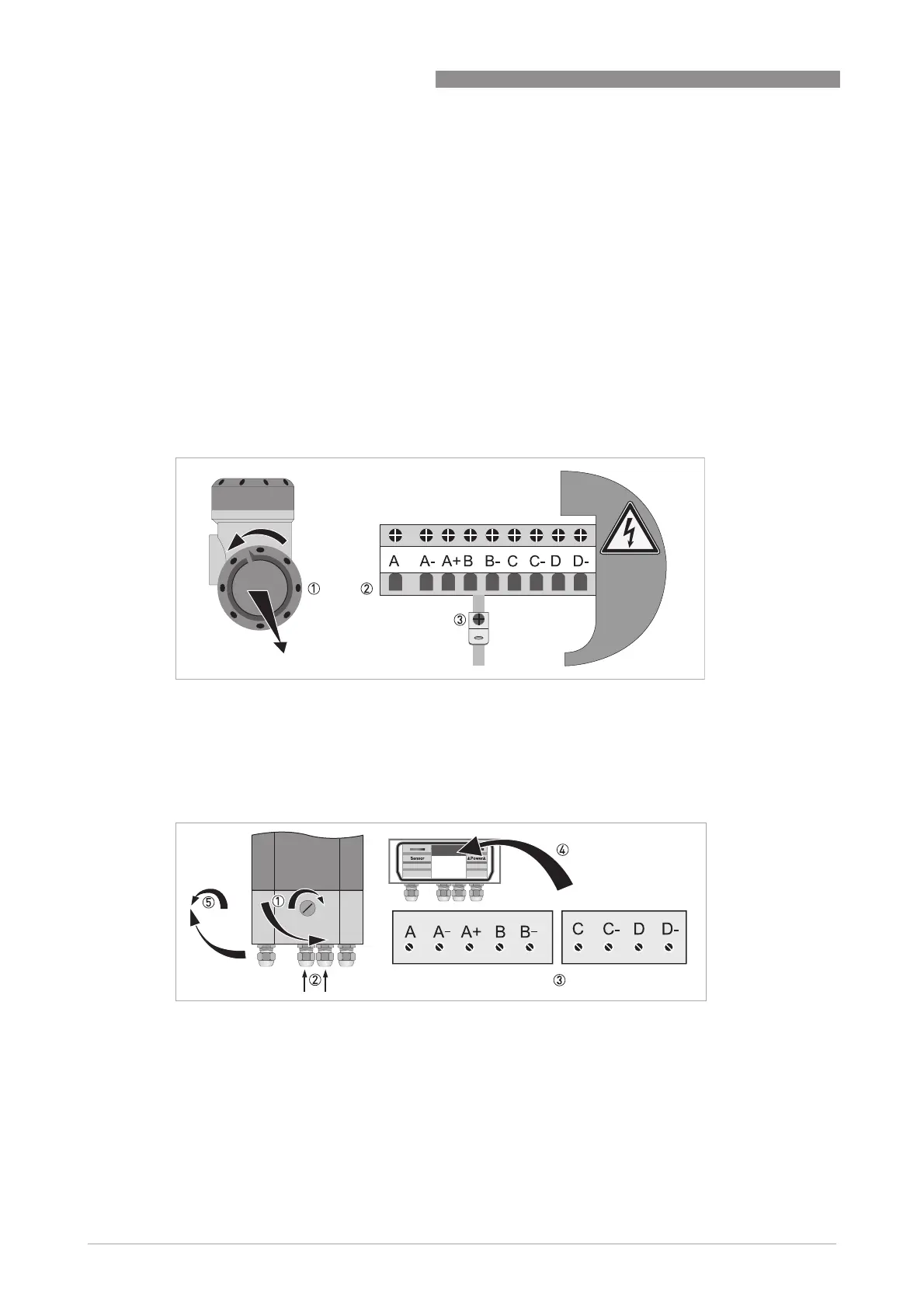
• Open the housing cover 1 and remove.
• Push the prepared cable through the cable entry and connect the necessary conductors 2.
• Connect the shield if necessary 3.
• Open the lock of the housing cover 1 with screw driver (clockwise).
• Open bottom cover (terminal compartment).
• Push the prepared cable through the cable entry 2 and connect the necessary conductors 3.
• Connect the shield if necessary 4.
• Close the cover of the terminal compartment.
• Lock 5 the housing cover with screw driver (counter clockwise).
All work on the electrical connections may only be carried out with the power disconnected.
Take note
of the
voltage data
on
the nameplate!
Observe connection polarity.
)RUIUHTXHQFLHVDERYH+]VKLHOGHGFDEOHVDUHWREHXVHGLQRUGHUWRUHGXFHHIIHFWVIURP
HOHFWULFDOLQWHUIHUHQFHV(0&
Each
time a housing cover is
opened, the thread should
be cleaned and greased. Use only resin-
free
and acid-free grease.Ensure that the housing gasket
is properly fitted, clean and
undamaged.
Field version
Figure 4-13: Terminal compartment for inputs and outputs of the field housing
Wall version
Figure 4-14: Terminal compartment for inputs and outputs of the wall-mounted housing