4 ELECTRICAL CONNECTIONS
52
OPTISONIC 6300
www.krohne.com 09/2020 - 4006413102 - TD OPTISONIC 6300 V2 R02 en
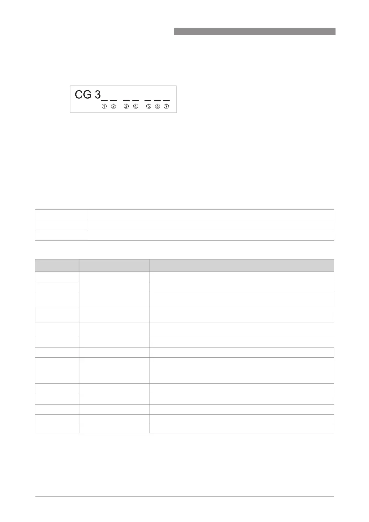
4.5.2 Description of the CG-number
The last 3 digits of the CG number (5, 6 and 7) indicate the assignment of the terminal
connections.Please refer to the following examples.
Examples for CG number
Description of abbreviations and CG identifier for possible optional modules on terminals A and B
Figure 4-15: Marking (CG number) of the electronics module and input/output variants
1 ID number:7
2 ID number: 0 = standard
3 Power supply option
4 Display (language versions)
5 Input/output version (I/O)
6 1st optional module for connection terminal A
7 2nd optional module for connection terminal B
CG 370 x1 100 100...230 VAC & standard display; basic I/O: I
a
or I
p
& S
p
/C
p
& S
p
& P
p
/S
p
CG 370 x1 7FK 100...230 VAC & standard display; modular I/O: I
a
& P
N
/S
N
and optional module P
N
/S
N
& C
N
CG 370 x1 4EB 24 VDC & standard display; modular I/O: I
a
& P
a
/S
a
and optional module P
p
/S
p
& I
p
Abbreviation Identifier for CG No. Description
I
a
A Active current output
I
p
B Passive current output
P
a
/ S
a
C Active pulse output, frequency output, status output or limit switch
(changeable)
P
p
/ S
p
E Passive pulse output, frequency output, status output or limit switch
(changeable)
P
N
/ S
N
F Passive pulse output, frequency output, status output or limit switch acc.
to NAMUR (changeable)
C
a
G Active control input
C
p
K Passive control input
C
N
H Active control input to NAMUR
Signal converter monitors cable breaks and short circuits acc. to NAMUR
EN 60947-5-6. Errors indicated on LC display. Error messages possible
via status output.
IIn
a
P Active current input
IIn
p
R Passive current input
2 x IIn
a
5 Two active current inputs (for Ex i I/O)
- 8 No additional module installed
- 0 No further module possible