Do you have a question about the KROHNE OPTISONIC 7300 and is the answer not in the manual?
Check packing list and inspect packaging for damages.
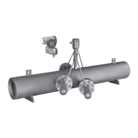
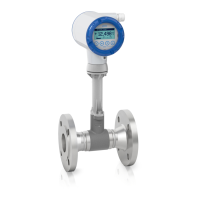
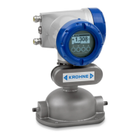
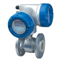
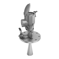
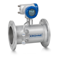
Details ultrasonic flowmeters' design and available versions (compact/remote).
Information on device nameplates for compact and remote versions.
Illustrates nameplate details for the compact version.
Shows nameplate information for the flow sensor in the remote version.
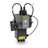
Details nameplate information for the signal converter in the field housing.
Provides connection data for inputs/outputs, including terminal assignments.
Guidelines for storing the device, including environmental conditions.
Instructions for safely transporting the signal converter and flow sensor.
Lists necessary tools and provisions for a quick, safe installation.
Precautions for reliable installation, including space, sunlight, and vibration.
Guidelines on avoiding intense vibrations for reliable operation.
Guidelines for optimal flowmeter function, especially for dry gas flow.
Specifies recommended inlet/outlet lengths and T-section distances.
Recommended inlet/outlet pipe lengths for different flowmeter sizes.
Specifies required distance behind a T-section for proper flow measurement.
Guidance on installing flowmeter upstream of control valve to avoid noise.
Defines maximum permissible deviation for pipe flange faces.
Details allowed horizontal/vertical installation positions for liquid and dry gas flows.
Precautions for thermal insulation, emphasizing leaving vent holes free.
Instructions for mounting the signal converter (field housing) onto a pipe.
Step-by-step guide for fixing the signal converter to the pipe using U-bolts.
Procedure for rotating the display of the field housing version in 90° increments.
Critical safety warnings for electrical connections, including power disconnection.
Details connecting signal cables between flow sensor and signal converter for remote versions.
Instructions for connecting power supply, including warnings for hazardous areas.
Best practices for routing and protecting electrical cables.
Overview of available input/output combinations for the signal converter.
Details various input/output combinations for the signal converter.
Explains CG number structure for electronics module and I/O variants.
Presents fixed I/O configurations and their terminal assignments.
Lists alterable I/O versions and terminal assignments.
Provides dimensions and weight for remote and compact signal converter housings.
Tables for dimensions and weight of carbon steel flow sensors (EN 1092-1, PN 16).
Dimensions and weight specifications for PN 40 flow sensors.
Dimensions and weight specifications for ASME 150 lb flow sensors.
Dimensions and weight specifications for ASME 300 lb flow sensors.
Dimensions and weight specifications for ASME 600 lb flow sensors.
Dimensions and weight specifications for ASME 900 lb flow sensors.
Provides dimensions and weight for compact and field signal converter housings.
Details dimensions of the mounting plate for the field housing.
| Type | Ultrasonic Flowmeter |
|---|---|
| Accuracy | ±0.5% of measured value |
| Measurement Range | 0.01…25 m/s / 0.03…82 ft/s |
| Temperature Range | -40°C to +200°C |
| Output Signal | 4-20 mA, Modbus |
| Power Supply | 24 V DC, 100-240 V AC |
| Enclosure Rating | IP66/67 |
| Material | Stainless steel |
| Certifications | ATEX, IECEx |
| Typical Applications | Water, Wastewater, Chemicals, Food and Beverages |
| Measurement Principle | Ultrasonic transit time difference |
| Repeatability | ±0.2% of reading |