CONTENTS
2
www.krohne.com 09/2018 - 4002312802 - QS OPTISONIC 7300 R04 en
OPTISONIC 7300
1 Safety instructions 3
2 Installation 4
2.1 Scope of delivery............................................................................................................... 4
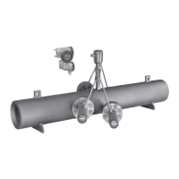
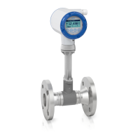
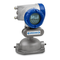
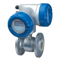
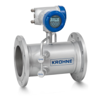
2.2 Device description ............................................................................................................ 5
2.3 Nameplates ...................................................................................................................... 6
2.3.1 Example of nameplate for the compact version .................................................................... 6
2.3.2 Example of nameplate for the flow sensor (remote version) ................................................ 6
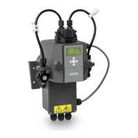
2.3.3 Examples of nameplates on the signal converter (field housing) ......................................... 7
2.4 Storage ............................................................................................................................. 9
2.5 Transport .......................................................................................................................... 9
2.6 Pre-installation requirements ......................................................................................... 9
2.7 General requirements.................................................................................................... 10
2.7.1 Vibration ................................................................................................................................ 10
2.8 Installation requirements for the flow sensor............................................................... 10
2.9 Installation conditions ....................................................................................................11
2.9.1 Inlet and outlet...................................................................................................................... 11
2.9.2 T-section ............................................................................................................................... 11
2.9.3 Control valve ......................................................................................................................... 12
2.9.4 Flange deviation.................................................................................................................... 12
2.9.5 Installation position .............................................................................................................. 13
2.9.6 Thermal insulation................................................................................................................ 14
2.10 Mounting the field housing, remote version ................................................................ 15
2.10.1 Pipe mounting ..................................................................................................................... 15
2.10.2 Turning the display of the field housing version ................................................................ 16
3 Electrical connections 17
3.1 Safety instructions.......................................................................................................... 17
3.2 Connection of signal cable to signal converter (remote version only).......................... 17
3.3 Power supply connection ............................................................................................... 19
3.4 Laying electrical cables correctly .................................................................................. 20
3.5 Inputs and outputs, overview ......................................................................................... 21
3.5.1 Combinations of the inputs/outputs (I/Os) ........................................................................... 21
3.5.2 Description of the CG number .............................................................................................. 22
3.5.3 Fixed, non-alterable input/output versions.......................................................................... 23
3.5.4 Alterable input/output versions............................................................................................ 24
4 Technical data 25
4.1 Dimensions and weight .................................................................................................. 25
4.1.1 Flow sensor in carbon steel.................................................................................................. 26
4.1.2 Signal converter housing ...................................................................................................... 30
4.1.3 Mounting plate of field housing ............................................................................................ 31