Do you have a question about the KROHNE OPTIWAVE-M 7400 and is the answer not in the manual?
Lists ATEX compliance standards and certification details for the device, including EU-Type Examination Certificate.
Explains the markings and information present on the ATEX nameplate, crucial for identification and compliance.
Provides essential safety precautions for installation, including general notes and electrostatic discharge hazards.
Warns about electrostatic discharge hazards from the antenna and painted surfaces, and locations to avoid.
Details temperature class limits for ambient and process connections, including specific notes for antenna types.
Instructions for connecting the device to the equipotential bonding system for hazardous location safety.
Lists the maximum intrinsically-safe values for the electrical circuit for level transmitters (Ui, Ii, Pi, Ci, Li).
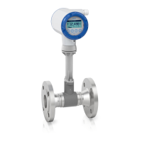
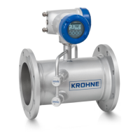
The OPTIWAVE-M 7400 is a radar level transmitter designed for measuring level, volume, distance to surface, and reflectivity of liquids, pastes, and slurries. This device is approved for use in potentially explosive atmospheres when equipped with the appropriate options, conforming to European Directive 2014/34/EU (ATEX 114) and certified by Kiwa ExVision B.V. under EU-Type Examination Certificate KIWA 17ATEX0026 X.
The primary function of the OPTIWAVE-M 7400 is to provide accurate and reliable measurements of various fluid properties in industrial processes. It utilizes radar technology to achieve non-contact measurement, making it suitable for a wide range of applications. The device can display measurements via a Device Type Manager (DTM) for remote communication or on an optional integrated display screen with a wizard-driven setup, enhancing user interaction and configuration. An external transmitter for measuring process pressure is also available as an option, further expanding its capabilities.
The device is marked for use in potentially explosive atmospheres with specific categories and temperature classes. For the PP Drop antenna, the marking is II 1/2 G Ex ia IIC T6...T5 Ga/Gb. For all other versions, it is II 1/2 G Ex ia IIC T6...T3 Ga/Gb. This indicates suitability for Gas Groups IIA, IIB, and IIC, and for applications requiring Category 1/2 G and EPL Ga/Gb or Category 2 G and EPL Gb equipment. The temperature classes range from T6 to T1, provided the specified temperature limits are observed.
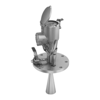
The device is designed for installation in boundary walls between Zone 0 and Zone 1, with the antenna in Zone 0 and the signal converter in Zone 1 for Category 1/2 G equipment. Category 2 G equipment is used in Zone 1. It is crucial to ensure that the installation between Zone 0 and Zone 1 complies with EN 60079-26.
Electrical connections are intrinsically safe. The maximum intrinsically-safe values for the 4-20 mA passive – HART output are:
The minimum supply voltage at output terminals is 12 V DC, and the maximum is 30 V DC. The terminal tightening capacity for flexible or rigid wires is 2.5 mm² (13 AWG). The device electronics are isolated with a rating of 500 VRMS.
Ambient and process connection temperatures are critical for safe operation. For T6, the maximum ambient temperature is +60°C (or +53°C) with a maximum process connection temperature of +60°C (or +85°C). For T5, these are +75°C (or +68°C) and +75°C (or +100°C) respectively. For T4, they are +71°C (or +65°C) and +115°C (or +135°C). For T3, they are +62°C (or +54°C or +49°C) and +150°C (or +180°C or +200°C). If the device has a PP Drop antenna, the maximum process connection temperature for T4 is +100°C. If it has a PTFE Drop antenna, the maximum process connection temperature for T3 is +150°C. The minimum process connection temperature for all classes is -40°C, or -20°C if a Kalrez® gasket is used.
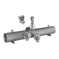
The OPTIWAVE-M 7400 can be installed on auxiliary equipment such as bypass chambers, stilling wells, or communicating pipes. An optional purging system is available for devices with horn antennas, requiring a 1/4 NPTF purging connection. If a purging system is used, the purging fluid temperature must be less than the ignition temperature of the gas or vapor atmosphere and within the gasket's temperature limits.
Installation requires careful attention to electrostatic discharge (ESD) risks, especially from the Drop antenna and painted surfaces. The device should not be installed near ventilation systems, sources of compressed air and dust, friction-generating machines, or electrostatic painting systems. All personnel and equipment must be correctly grounded.
Electrical connections must be made with the circuit de-energized, using appropriate cable glands (M20x1.5 or M25x1.5) as specified on the device nameplate. The device must be connected to the equipotential bonding system of the hazardous location, either via an internal ground terminal in the terminal compartment or an external ground terminal adjacent to the cable entries. The process connection can also serve as an equipotential bonding point, provided there is a good electrical connection.
Under normal operational conditions, the OPTIWAVE-M 7400 requires no periodic maintenance. Repairs and component replacements must only be performed by the manufacturer or approved personnel trained in explosion protection. It is crucial not to replace an Ex i electronic block with one from a device without an intrinsically-safe barrier.
The device must be kept clean to prevent dust contamination. Cleaning should be done with a damp cloth; compressed air should not be used. If dirt collects on the device, it must be cleaned with a damp cloth. Care must be taken to avoid cleaning agents that could damage the paint, the PTFE process seal, EPDM housing gaskets, or process connection gaskets (FKM/FPM or Kalrez®). Cleaning agents must not remove data printed on the nameplate.
When returning the device to the manufacturer for inspection or repair, strict adherence to safety regulations is required. If the device has been in contact with toxic, caustic, radioactive, flammable, or water-endangering products, all cavities must be checked, rinsed, or neutralized to ensure they are free from dangerous substances. A certificate confirming the device is safe to handle and stating the product used must accompany the returned device. This certificate must be accessible from outside the packaging.
The signal converter of an OPTIWAVE 8300 level transmitter with an Ex approval (KEMA 04ATEX1218 X) can be replaced, provided an intrinsically-safe barrier and correct electrical wires are used, and the signal converter was not installed in Zone 0 or Zone 20. If an unserviceable OPTIWAVE 8300 has a Drop antenna, the signal converter should not be replaced; instead, the entire device should be replaced. An adaptor is required when replacing the signal converter with an OPTIWAVE-M 7400 signal converter.
| Brand | KROHNE |
|---|---|
| Model | OPTIWAVE-M 7400 |
| Category | Measuring Instruments |
| Language | English |