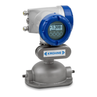
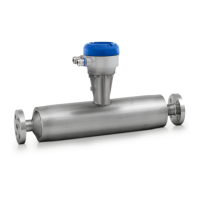
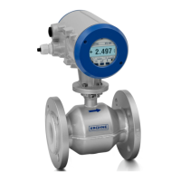
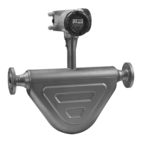
The OPTIMASS 6400 is a 4-wire Coriolis mass flowmeter designed for measuring mass flow rate, total mass, density, temperature, volume flow rate, flow velocity, total volume, and concentration of liquids and gases. It is specifically designed for use in safety applications, providing a safe current output (4 to 20 mA) for mass flow, volume flow, or density measurements. The device is approved for Safety Integrity Level (SIL) 2 in single-channel architecture and SIL 3 in homogeneous redundancy architecture according to IEC 61508.
Function Description:
The core safety function of the OPTIMASS 6400 is to provide a correct mass flow, volume flow, or density measurement on its safe current output (terminal C) within a tolerance of ±2% and within the specified process response time. This safe current output is available in both intrinsically safe and non-intrinsically safe variants, compliant with IEC 60079-11. The device continuously monitors its internal state and process conditions to ensure the integrity of the safety function. In the event of a detected safe or dangerous failure, the device will transition to a safe state, setting the current output to a preferred failure current (≤ 3.6 mA or ≥ 21 mA, with the low failure current being the definitive safe state signal for hardware failures).
Important Technical Specifications:
- Measurement Range: The device measures mass flow rate, total mass, density, temperature, volume flow rate, flow velocity, total volume, and concentration.
- Safe Current Output: 4-20 mA, with a tolerance of ±2% for safety applications.
- Process Response Time (T90): Varies based on damping settings, from 0.90 s (0 s damping) to 181.74 s (100 s damping).
- Measurement Uncertainty: Equivalent to non-SIL operation as described in the handbooks, with a safety tolerance for random errors of up to 2% of the present measurement value or output current before a signal is issued.
- Safety Integrity Level (SIL):
- Single channel (HFT = 0): SIL 2
- Homogeneous redundant (HFT = 1): SIL 3
- Hardware Fault Tolerance (HFT): 0 (for SIL 2) and 1 (for SIL 3).
- Architecture: 1oo1 with diagnostics.
- Probability of a Dangerous Failure per Hour (PFH):
- I/O option 2 or 3: 4.50E-08
- I/O option 4: 4.42E-08
- Safe Failure Fraction (SFF):
- I/O option 2 or 3: 96.59%
- I/O option 4: 96.65%
- Average Probability of Failure on Demand (PFDAVG):
- TProof = 1 year: 3.9E-04
- TProof = 3 years: 1.2E-03
- TProof = 5 years: 2.0E-03
- Proof Test Coverage (PTC): Up to 97%.
- Diagnostic Test Interval: 1 min.
- Fault Reaction Time: 1 s.
- Power Supply Options: 100-230 VAC or 12-24 VDC.
- I/O Options: Various connection terminals including I active, I passive, P/S NAMUR C passive, I + HART® active/passive, and P/S active/passive. The current output at terminal C is the safety-relevant output.
- Flow Sensor Variants: Identified by a V number on the nameplate, with specific codes for flow sensor type and size, design (K only), process requirements (0 or 1), and signal converter type (6 or 7).
Usage Features:
The device operates in different safety modes: "Non-SIL operation," "Safe configuration," and "Safe operation."
- Non-SIL Operation: All parameters can be changed, and the current output provides a measurement or failure signal.
- Safe Configuration: The device can be configured for safe operation or switched to non-SIL mode. The current output provides a failure signal. During this state, certain safety-relevant parameters are reset to factory values and locked, including current span (4-20 mA), polarity (both), trim values (disabled), loop current mode (enabled), operation mode (enabled), density calibration (factory), operation mode (measurement), pressure suppression (disabled), density mode (process), sensor low flow cutoff (factory setting), process noise damping (1.0 s), flow offset (0 kg/s), and flow correction (0%). Other changeable safety-relevant parameters, such as device tag, measurement variable, range values, alarm code, low flow cutoff, damping, terminal C type, flow direction, and zero calibration, must be configured.
- Safe Operation: The device performs safe measurements, and all safety-relevant parameters are locked. The current output provides a measurement or failure signal.
- Switching to Safe Operation: Requires setting the safety mode to "SIL Mode," configuring the device, and performing a safe parameter verification. This verification process involves reviewing all safety-relevant parameters via local display or HART® interface and confirming the configuration with a random 3-digit key.
- Switching to Non-SIL Operation: Requires unlocking the device, changing the safety mode to "Non-SIL Mode," and confirming the change.
- Unlock Feature: Safety-relevant parameters can only be changed in "Safe configuration" mode, which is entered by unlocking the device using a configurable unlock key (default: 9999).
- Safety State Indication: The current safety state (Safe configuration or Safe operation) is displayed with an icon on the local display.
- Error Handling: The device distinguishes between safety-relevant failures (leading to a safe state) and non-safety-relevant faults. Specific error messages and corresponding actions are provided, such as "Electr.Temp.Out of Spec," "Flow Out of Range," "IO Connection," "Int. Comm. Error IO C," "IO C Failure," "Process Input Failure," "Safe Config. Invalid," "Safety Rel. Failure," "Sensor Error," and "Temp. Or Strain Res. Def."
- Environmental Conditions: Must be operated within specified process and ambient conditions. Restrictions include avoiding entrained gas, cavitation, corrosive/erosive products, and coating inside the measurement tube.
Maintenance Features:
- Periodic Maintenance: Follow instructions in the device handbook.
- Cleaning: Refer to the "Service" section in the handbook.
- Spare Parts Availability: Functionally adequate spare parts are available for 3 years after the last production run, covering wear and tear under normal operating conditions.
- Proof Test: Essential for maintaining SIL compliance. SIS engineers must calculate the interval based on the required PFDAVG. Customer-performed proof tests must cover at least the following steps:
- Perform a power cycle.
- Perform a 4-point current output check (3.6 mA, 4.0 mA, 20.0 mA, 21.5 mA) using the built-in simulation function and measure the current with a traceably-calibrated ammeter (uncertainty ±5 μA or better).
- Compare density reading with the expected product density, ensuring measurement uncertainty does not exceed the maximum error specified in the handbook.
- Check mass flow measurement accuracy with a calibration rig (at least 2 measuring points) or return the device to the manufacturer for recalibration.
- Proof Test Coverage: 77% (partial, steps 1-2), 82% (partial, steps 1-3), 97% (full, steps 1-4). KROHNE OPTICHECK can assist with tests 1-3.
- An optical inspection of sealings, containment, housing, and electrical wiring is required during every proof test.
- Detailed reports of each proof test must be kept.
- Calibration Procedure: A zero calibration is recommended during every proof test or safe configuration, following conditions in the handbook. In safe operation, factory density calibration is used.
- Troubleshooting: Modifications to SIL-capable devices by the user are not permitted. Only authorized manufacturer personnel can repair the device. Critical failures should be reported to technical support.