OPERATION
4
15
OPTIMASS 6400
www.krohne.com11/2017 - 4004960802 - AD OPTIMASS 6400 SIL R02 en
4.2.7 Unlock of device
Safety relevant parameters cannot be changed in safe operation. The device must be set to the
safety state safe configuration in order to change safety relevant parameters. Therefore unlock
the device (C7.4) by entering the configurable unlock key (C7.5). Within this state the current
output is set to the failure signal.
Default Unlock Key:
Default Unlock Key:Default Unlock Key:
Default Unlock Key: 9999
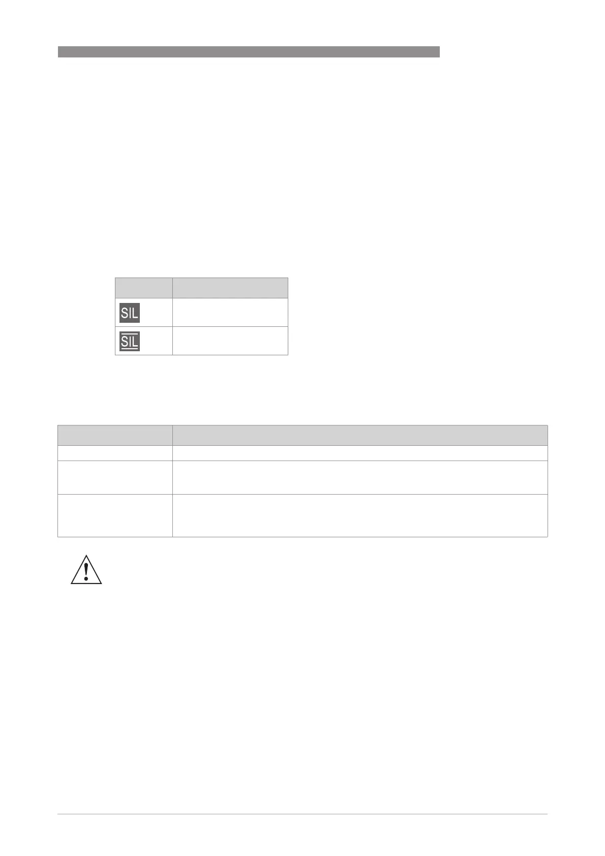
4.2.8 Current safety state of the device
Current safety state of the device is displayed at local display with an icon in the upper right
corner:
Furthermore check menu entry B1.6 for present safety state.
4.3 Safe current output states
Icon State
Safe configuration
Safe operation
Current output state Description
Measurement (4-20 mA) Output of safe measurement.
Extended Range
(3.8…20.5 mA)
Output according to NE43 [N5]. If the limits of the extended range are reached, the device
sets the signal "Out of Specification" (current output) however it does not enter the safe
state.
Safe State (≥ 21 mA or
≤ 3.6 mA)
For any type of safe or dangerous detected failure, the device sets the safe current output
to the preferred failure current (failure signal). Although this value can also be set to high
failure current (≥ 21 mA) some hardware failures will always cause the device to set a low
failure current (≤ 3.6 mA). Thus, the output signal for the safe state is less than 3.6 mA.
WARNING!
If the device is used in a safety loop both the high and low failure current must be monitored.