2
SPECIFICATION OF THE SAFETY FUNCTION
8
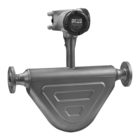
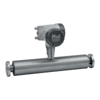
OPTIMASS 6400
www.krohne.com 11/2017 - 4004960802 - AD OPTIMASS 6400 SIL R02 en
2.1 Preconditions
The device must be operated within the process and ambient conditions specified in the
handbooks ([N1], [N2]) of the device.
In addition the device has the following restrictions for safety applications:
• Ensure that entrained gas, cavitation of two-phase flows do not occur in the flowmeter.
• Corrosive products must be excluded according to [N4].
• Erosive products must be excluded.
• Coating inside the measurement tube must be avoided.
In order to execute the safety function the device must be switched to safe operation (for further
information refer to
Switch to safe operation
on page 11).
2.2 Definition of the safety function
The safety function of the device is:
Put out a correct mass flow or volume flow or density measurement on safe current output (4 to
20 mA) with a tolerance of ±2% within the process response time of the device (for further
information refer to
Process response time
on page 8).
2.2.1 Process response time
The process response time is defined as the T90 for a response to a step change between
process input and safe current output. It depends on the configured time constant of the
damping in the safe current output (C7.1.16):
2.2.2 Measurement uncertainties
The measurement uncertainty of the device in safe operation equals to those in non-SIL
operation as described in the handbooks ([N1], [N2]). It consists of the uncertainty of
measurement function and current output.
Concerning random errors in the device, the safety tolerance must be considered. The safety
tolerance is the tolerable error before setting the safe state of the device. A random fault can
cause an error of up to 2% of the present measurement value or output current before it is
signalled.
Damping [s]
Damping [s]Damping [s]
Damping [s] 0 1 2 5 10 20 50 100
T90 [s]
T90 [s]T90 [s]
T90 [s] 0.90 2.38 4.16 9.58 18.63 36.75 91.12 181.74