SERVICE
5
17
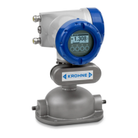
OPTIMASS 6400
www.krohne.com11/2017 - 4004960802 - AD OPTIMASS 6400 SIL R02 en
5.1 Periodic maintenance
You must follow the maintenance instructions given in the handbook [N1].
5.2 Keep the device clean
For further information refer to "Service" in the handbook ([N1]).
5.3 Spare parts availability
The manufacturer adheres to the basic principle that functionally adequate spare parts for each
device or each important accessory part will be kept available for a period of 3 years after
delivery of the last production run for the device.
This regulation only applies to spare parts which are subject to wear and tear under normal
operating conditions.
5.4 Proof test
Keep a report of each proof test. These reports must include the date, the tests results
(performance of the safety function or faults found), a list of approved personnel who did the test
and the report revision number. These reports must be put into storage and made easily
available. If any test step fails because specified tolerances are exceeded, the safety function of
the device is not fulfilled anymore. Please return the device to the manufacturer [N2].
Test procedure
Unlock device and set it to non-SIL operation.
Set the device to safe operation.
WARNING!
SIS engineers must calculate the interval of proof tests based on the required PFD
AVG
.
CAUTION!
Proof tests done by the customer must cover at least the tests given in this section.
Step Measure
1 Perform power cycle (disconnect the device briefly from the power supply).
2 Perform a 4-point current output check for safe current output using the built-in simulation function
(B3.9), by setting the simulated current to 3.6 mA, 4.0 mA, 20.0 mA and 21.5 mA.
Measure the current at the current output with a traceably-calibrated ammeter or logic subsystem.
The ammeter must have a DC current measurement uncertainty ±5 µA or better.
3 Compare the density reading with the expected density of your product. The measurement uncertainty
must not exceed the maximum error specified in the handbook.
4 Check mass flow measurement accuracy with a calibration rig with at least at 2 measuring points or
return the device to the manufacturer for recalibration. The measurement uncertainty must not exceed
the maximum error specified in the handbook.