Do you have a question about the KROHNE OPTISWIRL 2100 and is the answer not in the manual?
Specifies the intended application and limitations of the vortex flowmeter.
Explains various danger, warning, and caution symbols.
General guidelines for safe installation and operation of the device.
Details the items included in the device package.
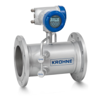
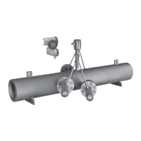
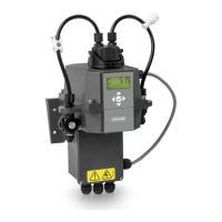
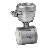
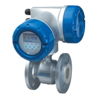
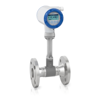
Lists the available variants of the device.
Explains the information presented on the device nameplate.
General information and precautions before installation.
Requirements for pipe filling, flow profile, and environmental factors.
Illustrates optimal mounting orientations for various pipe types.
Specifies required straight pipe lengths before the device.
General safety precautions for electrical work.
Step-by-step guide for connecting electrical components.
Proper grounding procedures for safety and measurement accuracy.
Describes the initial self-test and start-up screen.
Explains how to use the device via keys or magnet.
Explains fundamental operational concepts and key functions.
Introduces and details the device's menu structure.
Explains status signals and diagnostic information (NAMUR NE 107).
Procedure for replacing the signal converter unit.
Procedures for returning devices for inspection or repair.
Instructions for handling and disassembling the device for recycling.
Explains the Karman vortex street measuring principle.
General technical specifications for the device.
Provides dimensional and weight data for various device versions.
Tables showing measuring ranges for different media and conditions.
| Type | Vortex flowmeter |
|---|---|
| Nominal Diameter | DN 15 to DN 300 |
| Repeatability | ±0.2% of reading |
| Measurement Principle | Vortex shedding |
| Process Connection | Flange |
| Pressure Rating | PN 16 |
| Accuracy | ±1% of reading |
| Output Signal | 4-20 mA, pulse, frequency |
| Power Supply | 24 V DC |
| Protection Class | IP67 |
| Material | Stainless steel 1.4404 / 316L |
| Approvals | ATEX |
| Process Temperature | -200°C to +400°C |