2 INSTALLATION
8
OPTISONIC 7300
www.krohne.com 09/2018 - 4002312802 - QS OPTISONIC 7300 R04 en
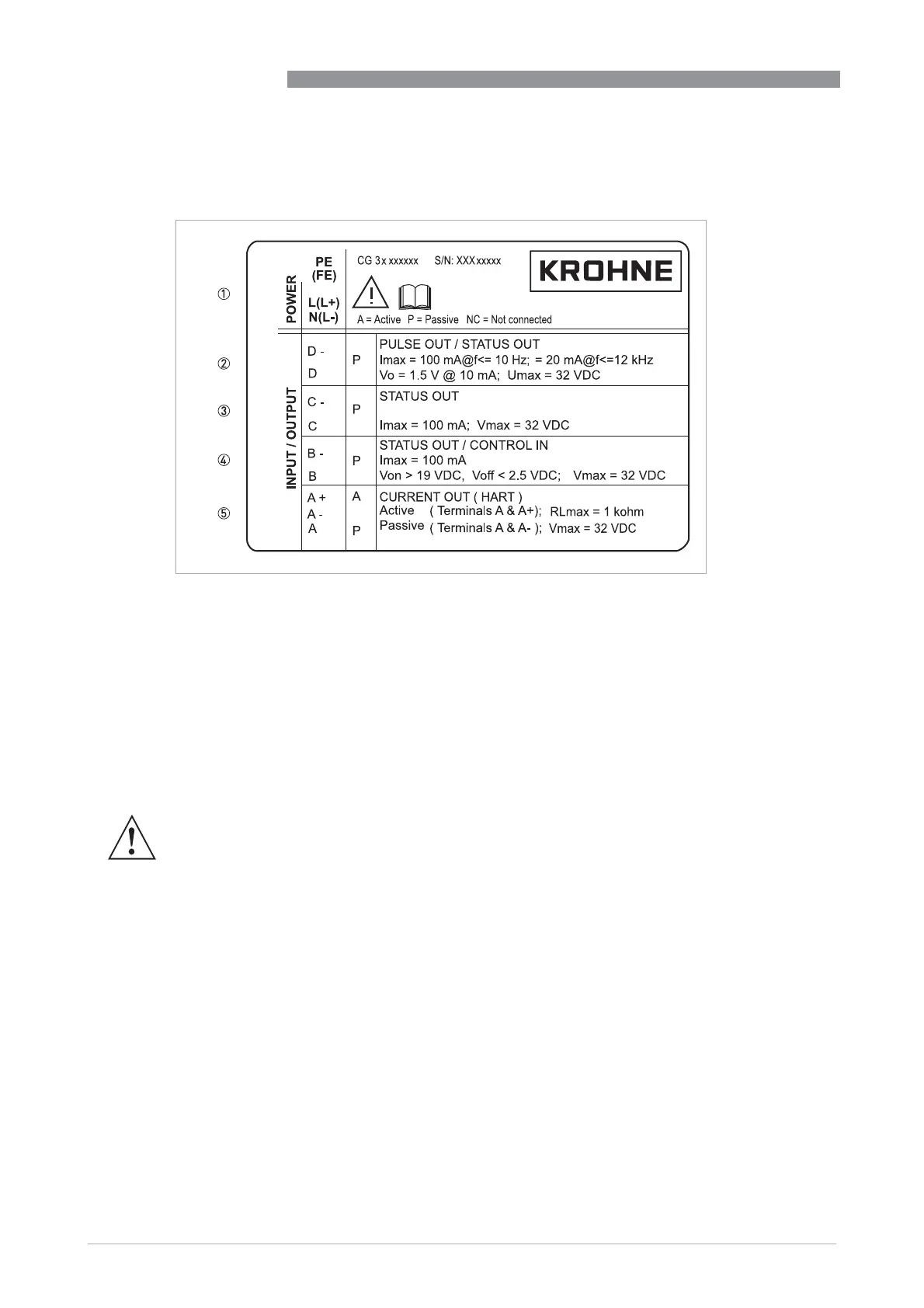
Electrical connection data of inputs/outputs (example of basic version)
Electrical connection data of inputs/outputs (example of basic version)Electrical connection data of inputs/outputs (example of basic version)
Electrical connection data of inputs/outputs (example of basic version)
• A = active mode; the signal converter supplies the power for connection of the subsequent
devices
• P = passive mode; external power supply required for operation of the subsequent devices
• N/C = connection terminals not connected
Figure 2-5: Example of a nameplate for electrical connection data of inputs and outputs
1 Power supply (AC: L and N; DC: L+ and L-; PE for t 24 VAC; FE for d 24 VAC and DC)
2 Connection data of connection terminal D/D-
3 Connection data of connection terminal C/C-
4 Connection data of connection terminal B/B-
5 Connection data of connection terminal A/A-; A+ only operable in the basic version
WARNING!
Do not use the terminals A+ and A- at the same time. The system will be damaged by the direct
voltage of 24 VDC and a 1 A peak current.