Do you have a question about the KROHNE ALTOSONIC 5 and is the answer not in the manual?
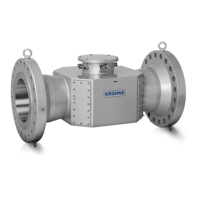
The KROHNE ALTOSONIC 5 is a highly accurate ultrasonic liquid flowmeter designed for custody transfer, fiscal, allocation, and leak detection applications. It consists of a flow sensor and a signal converter, both engineered to meet stringent explosion safety requirements.
The ALTOSONIC 5 operates on the principle of measuring the transit time of an ultrasonic sound wave. A series of intrinsically safe ultrasonic transducers are installed in the measuring tube of the flow sensor, with each pair forming an acoustic measurement path. The liquid velocity is derived from the difference in transit time of a sound wave traveling with and against the flow direction. The flow sensor utilizes an eight-path design, including a central path for optimal differentiation between turbulent, transition, or laminar flow, and a dedicated vertical diagnostic path for full pipe detection. The signal converter, housed in a flameproof/explosion-proof enclosure, processes the analog signals from the flow sensor and performs calculations for totalized volume, flow profiles diagnosis, and body temperature correction. It also supports integrated standard volume correction according to API 11.1, batching, and ticketing functionalities. The device offers configurable Smart IOs (4x or 8x) for digital or analog input/output, and communication via TCP/IP or Modbus (3 slaves, 1 master). An internal log system records relevant parameters, alarms, power failures, system loggings, parameter changes, and hardware changes, providing an audit trail for verification purposes.
The ALTOSONIC 5 is designed for fixed installations and requires careful attention to mounting position, pipe diameters, and inlet/outlet configurations. It is recommended to install the flow sensor with the flow arrow indicator in the direction of positive liquid flow and avoid installation at the highest point in the pipeline to prevent gas collection. Additional supports may be needed due to the significant weight of the flow sensor. Flow conditioners are preferred upstream to minimize perturbations, and if used, should be calibrated together with the inlet pipe and flow sensor. For applications without flow conditioners, KROHNE assistance is advised for inlet and outlet length determination. The device supports both unidirectional and bidirectional flow. Pressure and temperature sensors can be installed downstream, with specific considerations for bi-directional flow. The KROHNE Flowmeter Monitoring, Configuration and Diagnostics Tool (MCD) software package facilitates configuration, monitoring, and diagnostics from a PC. It allows users to collect and present data, verify/set/adjust parameters, and generate reports. Access rights are differentiated by user roles (Operator, Supervisor, Service, Calibrator, Factory) and protected by passwords. The MCD tool supports TCP/IP, Modbus, and USB communication.
The device is designed for ease of maintenance, with the signal converter featuring slide-in PCBs for easy replacement and removable cable connectors. Transducer servicing for Generation 1 flow sensors involves replacing inner parts without depressurizing the housing, using standard toolbox pliers and a special install tool. For Generation 2 flow sensors, the complete transducer can be removed using Allen hex keys, but the pipe must be empty and depressurized, and this should only be done by KROHNE personnel. The MCD tool provides functionalities for remote logging of process data, alarms, power failures, system loggings, parameter changes, and hardware changes, which aids in diagnostics and troubleshooting. Log files can be customized for content, log rate, time stamp, and storage location. The device is manufactured to be robust, with shock resistance of 15g for 6ms and vibration resistance of 1g up to 200 Hz. For carbon steel flow sensors, corrosion inhibitors or protective coatings are recommended during storage. KROHNE offers comprehensive services including repair, maintenance, technical support, and training. When returning a device for service, specific safety protocols must be followed, including providing a certificate confirming the device is safe to handle and using corrosion protection during transport.
| Brand | KROHNE |
|---|---|
| Model | ALTOSONIC 5 |
| Category | Measuring Instruments |
| Language | English |