Do you have a question about the KROHNE IFC 100 and is the answer not in the manual?
Explains the meaning of warning symbols and danger levels used in the manual.
Details essential safety precautions for personnel performing installation and maintenance.
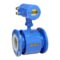
Defines the device's purpose and the items included in the delivery package.
Provides guidelines for proper storage conditions and safe transportation of the device.
Outlines environmental and spatial requirements for a successful installation.
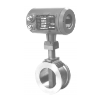
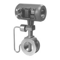
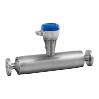
Instructions for direct mounting of the signal converter onto the measuring sensor.
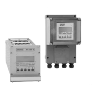
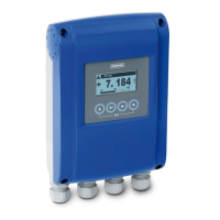
Steps for mounting the wall-mounted housing for remote signal converter versions.
Provides dimensions and mounting details for the wall-mounted version's mounting plate.
Crucial safety warnings and regulations for performing electrical connections.
Highlights essential precautions and configuration requirements for electrical connections.
Details regarding the construction, properties, and installation of signal cable A.
Important safety information and requirements for field current cable C.
Specifies electrical safety, capacitance, resistance, and test voltage requirements for customer cables.
General information on preparing signal cable A and field current cable C for connection.
Explains the structure and components of the double-shielded signal cable A.
Provides guidance on maximum signal cable lengths based on sensor type and conductivity.
Step-by-step instructions for preparing signal cable A for connection to the signal converter.
Details on preparing field current cable C and its required length and cross-section.
Instructions for preparing signal cable A to connect to the measuring sensor.
Steps for preparing field current cable C for connection to the measuring sensor.
General safety warnings and precautions for connecting signal and field current cables.
Instructions for opening the housing and connecting signal and field current cables to the converter.
Schematic diagram illustrating the connection of signal and field current cables.
Details on the classical method for grounding the measuring sensor and ensuring potential equalization.
Safety precautions and information on connecting the power supply to the signal converter.
Details the components and meaning of the CG number used for identification.
Describes the available fixed output combinations for the signal converter.
Step-by-step guide for making the electrical connections to the device's outputs.
Guidance on how to route electrical cables properly to protect the housing from environmental factors.
Checks and procedures required before switching on the power supply.
Describes the self-test process and initial operation after power-on.
| Type | Electromagnetic flowmeter |
|---|---|
| Repeatability | ±0.1% of measured value |
| Application | Water, wastewater |
| Display | LCD |
| Output | 4-20 mA, pulse, frequency |
| Communication | HART, PROFIBUS PA |
| Power Supply | 24 V DC |
| Protection Class | IP67 |
| Housing Material | Stainless steel |
| Nominal Diameter | DN2.5…3000 |
| Pressure Rating | Up to 40 bar / 580 psi |
| Accuracy | ±0.2% of measured value |