Do you have a question about the KROHNE OPTIFLUX Series and is the answer not in the manual?
Manufacturer's safety guidelines, disclaimer, warnings, and symbols.
Operator-specific safety precautions and compliance requirements.
Lists approval numbers for different OPTIFLUX configurations and converters.
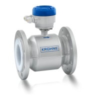
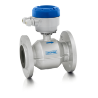
Details on OPTIFLUX 2000/4000 series, including Ex marking.
Ex marking details for OPTIFLUX 2000/4000 compact versions.
Ex marking details for OPTIFLUX 2000/4000 field versions.
Details on OPTIFLUX 5000 series, including Ex marking.
Ex marking details for OPTIFLUX 5000 compact versions.
Ex marking details for OPTIFLUX 5000 field versions.
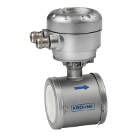
Details on OPTIFLUX 6000 series, including Ex marking.
Ex marking details for OPTIFLUX 6000 compact versions.
Ex marking details for OPTIFLUX 6000 field versions.
Details on OPTIFLUX 7000 series, including Ex marking.
Ex marking details for OPTIFLUX 7000 compact versions.
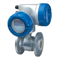
Details on the IFC 300 F signal converter and its Ex marking.
Information on sensor and converter marking labels.
Temperature limits for OPTIFLUX 2000/4000 models.
Temperature limits for OPTIFLUX 2000/4000 compact models.
Temperature limits for OPTIFLUX 2000/4000 field models.
Temperature limits for OPTIFLUX 5000 models.
Temperature limits for OPTIFLUX 5000 compact models.
Temperature limits for OPTIFLUX 5000 field models.
Temperature limits for OPTIFLUX 6000 models.
Temperature limits for OPTIFLUX 6000 compact models.
Temperature limits for OPTIFLUX 6000 field models.
Temperature limits for OPTIFLUX 7000 models.
Temperature limits for OPTIFLUX 7000 compact models.
Ambient temperature range for the IFC 300 F converter.
Construction details and EN standard for signal cable A.
Construction details and EN standard for signal cable B.
Requirements for equipotential bonding systems in hazardous areas.
Diagrams for connecting signal cables A and B.
Guidelines for installing equipment in explosive atmospheres.
Instructions for connecting the IFC 300 signal converter.
Details on signal I/O configurations for IFC 300 converters.
Recommendations for periodic inspections and housing checks.
Safety procedures for opening and closing the converter housing.
Steps for safely replacing the mains fuse.
| Measurement Principle | Electromagnetic Induction |
|---|---|
| Measuring Range | 0.01 to 12 m/s |
| Process Temperature | -40 to +180°C |
| Process Pressure | Up to 40 bar |
| Output Signals | 4...20 mA, pulse, frequency |
| Communication | HART, PROFIBUS DP/PA, Modbus, Foundation Fieldbus |
| Power Supply | 24 V DC, 100-240 V AC |
| Protection Class | IP67 |
| Accuracy | ±0.2% of measured value ±1 mm/s |
| Material | Stainless steel, PTFE |