8
T-Product · GIK, GIK..B · 2004 November
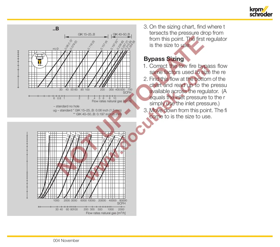
3. On the sizing chart, find where the corrected flow in-
tersects the pressure drop from Step 1. Move down
from this point. The first regulator curve you come to
is the size to use.
Bypass Sizing
1. Correct the low fire bypass flow you want with the
same factors used to size the regulator.
2. Find this flow at the bottom of the bypass orifice sizing
chart and read up to the pressure drop that will be
available across the regulator. (At low fire, this nearly
equals the inlet pressure to the regulator, so you can
simply use the inlet pressure.)
3. Move down from this point. The first orifice curve you
come to is the size to use.
Sizing
Flow rates natural gas [m
3
/h]
mbar
inch WC
Pressure drop ∆p
207 9 30 40 50 60 80 100
8 10
0.2 0.3 0.4 0.6 0.8 1 2
200 700300 400 500
3 4 5 6 8 10 20
SCFH
20
30
40
4
5
6
8
10
10
20
30
40
50
60
80
100
ø
GIK: bypass plug – standard no hole
GIK..B: bypass plug – standard * GIK 15–25..B: 0.06 inch (1,5 mm)
** GIK 40–50..B: 0.197 inch (5 mm)
Bypass screw GIK..B
inch (mm) Ø
0.06 (1.5)*
0.079 (2
)
0.118 (3
)
0.157 (4
)
0.197 (5)*
*
0.236 (6
)
0.267 (7
)
0.315 (8
)
0.354 (9)
GIK 15–25..B
GIK 40–50..B
inch WC
mbar
Pressure drop ∆p
2
3
4
5
6
8
1000 2000 3000 6000 10000 20000
Flow rates natural gas [m
3
/h]
SCFH
Flow rate
300 500
10 20 30 40 60 80100 200 300 500 1000
10
0.8
1
20
30
40
50
2
3
4
5
6
8
10
20
30
40
50
60
80
100
GIK 15
GIK 20
GIK 25
GIK 40
GIK 50
80000
40000
2000
G
IK
65
G
IK
80
G
IK 10
0
 Loading...