DK S N P GR
➔ www.docuthek.com
D GB F NL I E
TR CZ PL RUS H
© 2018 Elster GmbH · Edition 02.18
Cert. version 02.18
Safety
Please read and keep in a safe place
Please read through these instructions
carefully before installing or operating. Following the
installation, pass the instructions on to the opera-
tor. This unit must be installed and commissioned
in accordance with the regulations and standards
in force. These instructions can also be found at
www.docuthek.com.
Explanation of symbols
• , , , ... = Action
▷ = Instruction
Liability
We will not be held liable for damage resulting from
non-observance of the instructions and non-com-
pliant use.
Safety instructions
Information that is relevant for safety is indicated in
the instructions as follows:
DANGER
Indicates potentially fatal situations.
WARNING
Indicates possible danger to life and limb.
CAUTION
Indicates possible material damage.
All interventions may only be carried out by qualified
gas technicians. Electrical interventions may only be
carried out by qualified electricians.
Conversion, spare parts
All technical changes are prohibited. Only use OEM
spare parts.
Changes to edition 0.5
The following chapters have been changed:
– Installation
– Connection diagram
– Commissioning
– Assistance in the event of malfunction
– Certification
Contents
Operating instructions
GB-1
057
Translation from the German
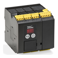
Burner control unit BCU 570
Burner control unit BCU 570..............
Contents ..............................
Safety.................................
Checking the usage .....................
Installation ............................
Replacing the power module/parameter
chip card ..............................
Cable selection.........................4
Wiring ................................4
Connection diagram ....................5
BCU 570 ..............................5
Flame control ...........................6
IC 20 connected to BCU570..F1............ 7
IC 20..E connected to BCU570..F1 .........8
IC 40 connected to BCU570..F1............9
RBW valve connected to BCU570..F2 ......10
Frequency converter connected to BCU570..
F2 .................................. 11
Adjustment ...........................
Commissioning........................
Manual mode .........................
Assistance in the event of malfunction ....
Replacing the fuse ......................18
Reading off the flame signal, fault
messages and the parameters...........9
Parameters and values...................19
Legend...............................
Technical data ........................
Designed lifetime .......................22
Logistics .............................
Accessories ..........................
Certification ..........................
Contact ..............................4
Safety
Contents