Do you have a question about the krom schroeder IFD 244 and is the answer not in the manual?
Instructions for installation and operation, must be kept safe and passed to operator.
Explains symbols used in the manual, such as action indicators and instructions.
Manufacturer disclaims liability for damages due to non-observance of instructions or non-compliant use.
Details how safety-relevant information is indicated using DANGER, WARNING, and CAUTION.
Prohibits technical changes and mandates use of OEM spare parts.
Describes the application of IFD 244/258 for burners in multi-burner applications.
Specifies the IFD..I variant with integrated ignition.
Details IFD 244 for gas burner monitoring with flame rod, including restart.
Covers IFD 258 for flame rod or UV sensor monitoring, intermittent UV operation.
Explains the coding system for IFD models, detailing ignition types and voltage options.
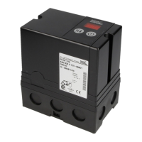
Identifies key components of the IFD unit using numbered labels and a diagram.
Provides instructions for installing the IFD unit, including position and connection points.
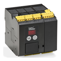
Highlights differences between the old IFS unit and the new IFD unit, like the display and fault signalling.
Specifies cable length and type for ionization control.
Specifies cable length and type for ignition.
Specifies cable length for UV control.
Guidance on preventing electromagnetic interference during cable installation.
Provides wiring diagrams for various IFD models and configurations.
Specific wiring details and diagram for IFD 244 and IFD 244..I models.
Wiring details and diagrams for IFD 258 models, including single-electrode operation.
Wiring details and diagrams for IFD 258..I models, focusing on UV control.
Explains the 7-segment display codes (00, 01, 02, 04) during the commissioning process.
Details how to adjust the IFD 258 for behavior in the event of flame failure.
Describes how to set the switch for immediate fault lock-out or automatic restart on IFD 258.
Guides users through identifying and resolving faults based on display codes and symptoms.
Addresses faults indicated by display code 01, related to incorrect flame signals or sensor issues.
Covers faults indicated by display code 02, concerning ignition spark, gas supply, or air in the pipeline.
Deals with faults when flame is present but ignition fails on start-up, indicating issues with flame signal or grounding.
Addresses faults indicated by display code 04, where operation is interrupted due to flame failure.
Covers various display codes indicating faults in input signals, resets, or internal errors.
Addresses system faults, permanent display issues, and conditions requiring manufacturer inspection.
Procedure for when the IFD does not start even after faults are remedied and the unit has been reset.
Lists and explains available parameters (01, 04, 12) for reading flame signal and burner settings.
Specifies environmental conditions, enclosure ratings, and mechanical dimensions for IFD units.
Details power consumption, output voltages, contact ratings, and signal input specifications.
States the designed lifetime for IFD 244 and IFD 258 units based on operating conditions.
Guidelines for protecting and transporting the IFD unit, including temperature and damage reporting.
Recommendations for storing the IFD unit, including duration, temperature, and humidity.
Declares compliance with EU directives and standards, listing relevant regulations.
Lists FM approval and its relevance to combustion safeguards and flame sensing systems.
Details UKCA certification and applicable British standards for gas appliances.
Confirms compliance with technical specifications for the Eurasian Customs Union.
Indicates compliance with the RoHS directive regarding hazardous substances in China.
Instructs on proper disposal according to WEEE Directive, avoiding domestic refuse and burning.
| Brand | krom schroeder |
|---|---|
| Model | IFD 244 |
| Category | Control Unit |
| Language | English |