IFD244, IFD258 · Edition 06.23
EN-11
14
Safety time during operation for gas valve
( 1; 2s)
22 Burner safety time on start-up ( 3; 5; 10s)
81
Last fault
82
Second to last occurring fault
83
Third to last occurring fault
84
Fourth to last occurring fault
… …
90
Tenth to last occurring fault
13 TECHNICAL DATA
Ambient conditions
Condensation and dew in and on the unit are not
permitted.
Avoid direct sunlight or radiation from red-hot sur-
faces on the unit.
Avoid corrosive influences, e.g. salty ambient air or
SO
2
.
Ambient temperature:
-20 to +60°C (-4 to +140°F).
Storage temperature:
-20 to +60°C (-4 to +140°F).
Transport temperature = ambient temperature.
Humidity: no condensation permitted.
Enclosure: IP 54 pursuant to IEC529.
Overvoltage category III pursuant to EN60730.
Permitted operating altitude: ‹ 2000m AMSL.
Mechanical data
Valve connections: 1.
Max. number of operating cycles:
reset button: 1000,
mains button: 1000,
signalling contacts: 250,000.
Length of sensor cable: max. 75m.
Length of ignition cable:
IFD: max. 5m, recommended ‹1m (with TZI/TGI),
IFD..I: max. 1m, recommended ‹0.7m.
Cable gland: M16.
Installation position as required.
Weight:
IFD: 610 g,
IFD..I: 770 g.
Electrical data
Power consumption:
IFD258: approx. 9VA,
IFD258..I: approx. 9VA + 25VA during ignition.
Output voltage for valves and ignition transformer =
mains voltage.
Contact rating:
Ignition output: max. 2A, cosφ = 0.2,
valve output: max. 1A, cosφ = 1,
signalling contacts: max. 2A, 253VAC,
total current for the simultaneous activation of the
valve outputs (terminals 11 and12) and of the igni-
tion transformer (terminal10): max. 2.5A.
Flame control:
sensor voltage: approx. 230V AC,
sensor current: > 2 μA,
max. ionization sensor current: ‹25μA.
Permissible UV sensors:
Elster Kromschröder models UVS1, 5, 6 and 10
for ambient temperatures from -40 to +80°C (-40
to +176°F).
IFD..I: ignition voltage: 22kVpp,
ignition current: 25mA,
spark gap: ≤ 2mm.
Fuses in unit:
F1: T 3.15A H 250V pursuant to IEC 127-2/5,
replaceable;
F2: 2AT to protect the valve outputs, not replace-
able.
Safety time on start-up t
SA
: 3, 5 or 10s.
Safety time during operation t
SB
: < 1s, < 2s.
Ignition time t
Z
: approx. 2, 3 or 6s.
IFD244
Mains voltage for grounded and ungrounded mains:
120VAC, -15/+10%, 50/60Hz,
230VAC, -15/+10%, 50/60Hz,
100VAC, -15/+10%, 50/60Hz.
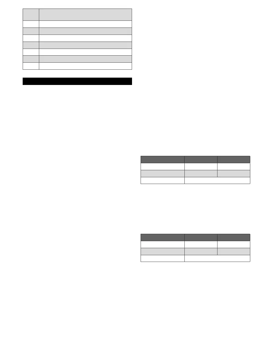
Signal inputs:
120V AC 230V AC
Signal “1” 80–132V 160–253V
Signal “0” 0–20V 0–40V
Frequency 50/60Hz
Input current of signal inputs: signal “1”: typ. 2mA.
IFD258
Mains voltage for grounded and ungrounded mains:
100VAC, -15/+10%, 50/60Hz,
120VAC, -15/+10%, 50/60Hz,
200VAC, -15/+10%, 50/60Hz,
230VAC, -15/+10%, 50/60Hz.
Signal inputs:
120V AC 230V AC
Signal “1” 80–132V 160–253V
Signal “0” 0–20V 0–40V
Frequency 50/60Hz
Input current of signal inputs: signal “1” = typ. 2mA
(reset),
‹ 2.5mA (terminal3).
Designed lifetime
This information on the designed lifetime is based
on using the product in accordance with these
operating instructions. Once the designed lifetime
has been reached, safety-relevant products must be
replaced.
Designed lifetime (based on date of manufacture) for
IFD244, IFD258: 10 years.

 Loading...