IFD244, IFD258 · Edition 06.23
EN-6
IFD244..I, IFD258..I
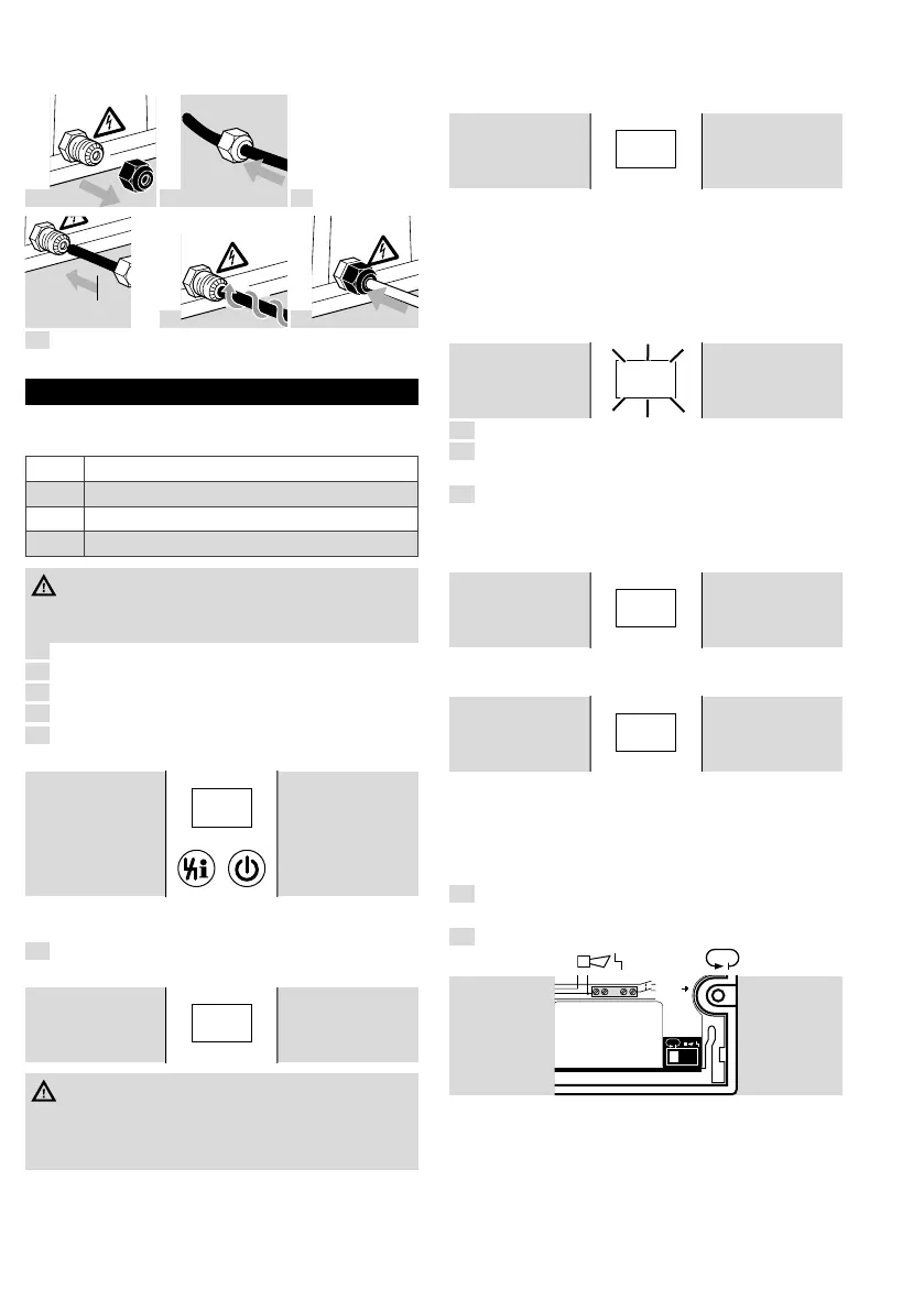
➔ Screw the ignition cable securely approx. 5cm
into the IFD..I onto a screw.
a
b
c
5
c
m
d
e
4
Replace the upper section and tighten.
8 COMMISSIONING
➔ During operation, the 7-segment display shows
the program status:
00
Start-up position
01
Waiting time
02
Safety time on start-up
04
Operation
DANGER
– Check the system for tightness before
commissioning.
1
Close the manual valve!
2
Switch on the system.
3
Apply voltage to terminal 1.
4
Check the electrical installation.
5
Switch on the IFD.
➔ The display indicates 00.
0 00 0
➔ The IFD retains its switch position when the
voltage is removed from terminal1.
6
Start the program for the burner: apply voltage
to terminal 3 – the display indicates 01.
0 1
WARNING
– The unit is defective if it opens a gas valve
during the waiting time (display01). Remove the
unit and return it to the manufacturer.
➔ ϑ signal minimum ON time (terminal3):
IFD..-3: 8s
IFD..-5: 10s
IFD..-10: 15s
The times must be at least this long, otherwise
the automatic burner control unit cannot monitor
the burner.
➔ Gas valve V1 opens, the burner ignites and the
display indicates02.
0 2
➔ Ignition time t
Z
:
IFD..-3: 2s
IFD..-5: 3s
IFD..-10: 6s
➔ After the safety time t
SA
(3, 5 or 10s) has
elapsed, the IFD signals a fault. The display
indicates a blinking 02.
0 2
7
Open the gas cock.
8
Reset the IFD by pressing the Reset/Information
button.
9
Start the program for the burner: apply voltage
to terminal 3.
➔ The display indicates 02, the gas valve V1 opens
and the burner ignites.
0 2
➔ After the safety time t
SA
(3, 5 or 10s) has
elapsed, the display indicates 04.
0 4
➔ IFD258: the contact between terminals 13 and
14 closes.
➔ The burner is in operation.
Adjustment
IFD258:
1
Undo the screws and remove the upper section.
Behaviour in the event of flame failure
2
Set the switch to the desired position (Immediate
fault lock-out
or Restart ).
L1, L2 = Live
N = Neutral
PE = Ground
1x
Single-electrode operation:
see operating instructions
L1 (L1)
N (L2)
PE
N
➔ At the factory, the IFD258 is set to Immediate
fault lock-out.
➔ Restart is recommended for burners which
occasionally display unstable flame behaviour.
Do not use with slow-closing air control valves
or continuous control, if the burner must not be
ignited at max. capacity, for burners with an out-
put of over 120kW in accordance with EN676.

 Loading...