Do you have a question about the krom schroeder IFD 258 and is the answer not in the manual?
General safety instructions for installation and operation. Keep for future reference.
Defines symbols used throughout the operating instructions.
States limitations of liability for damage due to non-observance of instructions.
Explains how safety information is indicated using DANGER, WARNING, and CAUTION.
Prohibits unauthorized technical changes and mandates the use of OEM spare parts.
Details the application range and variants of the IFD 244 and IFD 258 burner control units.
Explains the structure and meaning of the product's type code.
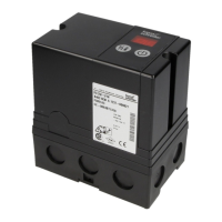
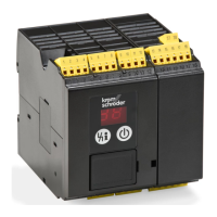
Identifies the physical parts and connections of the IFD unit.
General installation advice, including position requirements and safety precautions.
Lists compatible older IFS unit models that can be replaced by IFD units.
Details key functional differences and improvements of the IFD over the IFS.
Details specifications for mains, signal, control, ignition, and UV cables.
Addresses EMC reduction measures and proper cable installation practices.
Provides wiring instructions and connection diagrams for IFD units.
Explains the 7-segment display codes indicating program status during commissioning.
Detailed instructions for safe and correct commissioning of the burner control unit.
How to set the IFD 258 for immediate fault lock-out or automatic restart.
Details the process for adjusting the flame detection sensitivity.
Steps for verifying burner ignition and flame presence.
Essential safety measures before performing any maintenance work on the system.
Interprets various blinking display codes for fault diagnosis and resolution.
Procedures for checking the burner control unit's safety features.
Identifies and explains common blinking display codes and their potential causes.
How to read the flame signal and system parameters using the Reset/Information button.
Lists available parameters (01, 04, 12) and their corresponding values.
Specifies permissible ambient conditions, temperature, and humidity for operation.
Details mechanical specifications and electrical data, including power consumption and ratings.
Provides mains voltage ranges and signal input specifications for IFD 244 and IFD 258.
Information on the expected designed lifetime of the product.
Instructions for safe transport and storage of the unit.
Lists certifications such as CE, FM, UKCA, and RoHS compliance.
Guidelines for environmentally sound disposal of the product and its components.
The Kromschröder IFD 244 and IFD 258 are automatic burner control units designed for continuous operation in industrial burner applications. These units are suitable for both atmospheric and forced draught burners, particularly in multi-burner systems where a central control system manages pre-purge and monitors limits. They are ideal for direct ignition and monitoring of gas burners in continuous operation, and their fast reaction time makes them suitable for intermittent operation, adapting quickly to varying process requirements.
A key feature of these units is their 2-digit 7-segment display, which provides clear indications of the program status and flame signal intensity, aiding in monitoring and troubleshooting. The IFD..I models come with integrated ignition, simplifying the setup for certain applications. However, it is crucial to ensure that the high-voltage output of IFD..I models is protected against accidental contact. These models are not intended for domestic, commercial, or small firm applications due to potential electromagnetic interference.
The IFD 244 specifically monitors gas burners using a flame rod and is designed for grounded mains. It includes a restart function in the event of a flame failure, ensuring continuous operation where appropriate.
The IFD 258 offers more versatility, capable of monitoring gas burners with either a flame rod or a UV sensor. When used with UV sensors of Type UVS, the IFD 258 is intended for intermittent operation only, requiring an interruption in operation at least once every 24 hours. It supports ionization control in both grounded and ungrounded systems, and single-electrode ignition and monitoring are also possible. The cut-off point for flame detection can be adjusted via a potentiometer. Users can also select the unit's behavior in the event of a flame failure during operation, choosing between an immediate fault lock-out or an automatic restart. The specific mains voltage, ambient temperature, safety time, enclosure type, and for IFD..I models, ignition voltage (peak-peak) and ignition current, are detailed on the type label.
For ionization control, the maximum sensor cable length is 75 meters, while for UV control, it is 100 meters. In cases of automatic restart, it is essential that the program sequence aligns with the application and that the burner can restart as intended across all operating phases.
Installation of the IFD units is straightforward. They are designed to fit existing lower housing sections from previous IFS models, and the electrical connections remain unchanged. Eight knock-out holes are pre-prepared for wiring, accommodating M16 plastic cable glands for cables with 8 to 10 mm diameter. It is crucial to handle the device carefully during installation, as dropping it can cause permanent damage, necessitating replacement of the entire unit and its modules.
Maintenance features include a 7-segment display that shows program status, flame signal intensity, operating state, and flame simulation. The unit also provides fault signals when mains voltage is supplied. Additional protection functions are integrated to prevent over-frequent switching off during the safety time on start-up, over-frequent remote resets, and over-frequent cycling. A cycle lock mechanism is dependent on the start-up safety time and the ignition device.
When replacing older IFS 244 or IFS 258 units, only the specified IFD 244 or IFD 258 variants should be used. The housing dimensions and hole patterns have been maintained for compatibility.
Wiring requires suitable mains cables and signal/control lines, with specific recommendations for ionization and ignition cables to ensure proper performance and EMC reduction. It is vital to make a good PE (ground) wire connection to both the automatic burner control unit and the burner, especially for single-electrode operation, to prevent appliance damage. Voltage outputs and inputs must have the same polarity and not be reversed. Connections should be permanent, and L1, N, and PE must not be reversed. The reset function should not be set for automatic cycling.
Commissioning involves checking the system for tightness, closing manual valves, switching on the system, applying voltage, and checking electrical installation. The display guides the user through the start-up process, indicating program status such as "Start-up position," "Waiting time," "Safety time on start-up," and "Operation." A blinking "02" indicates a fault after the safety time has elapsed.
For adjustment, particularly with the IFD 258, the upper section can be removed to set the behavior in the event of flame failure (immediate fault lock-out or restart). While immediate fault lock-out is the factory default, restart is recommended for burners with occasionally unstable flame behavior, provided they do not use slow-closing air control valves or continuous control, and if the burner does not need to be ignited at maximum capacity, especially for burners over 120 kW according to EN 676.
Troubleshooting is facilitated by the display, which shows various fault codes (e.g., 01, 02, 04, 09, 10, 28, 29, 31, 32, 33, 52, 53, 83, 93, 81-99) to indicate specific issues such as incorrect flame signals, no gas supply, flame failure during start-up or operation, faulty inputs, internal device errors, low supply voltage, parameterization issues, or continuous resets. The manual provides detailed steps for diagnosing and remedying these faults, including checking wiring, replacing components, and adjusting settings.
The unit also allows for reading off the flame signal and parameters such as burner switch-off threshold and burner restart settings, providing valuable diagnostic information for maintenance and optimization.
| Type | IFD 258 |
|---|---|
| Category | Control Unit |
| Power Consumption | 10 VA |
| Operating Temperature | -20 to +60 °C |
| Manufacturer | Kromschroeder |