Do you have a question about the krom schroeder MPT 700 and is the answer not in the manual?
Information about the MPT 700's version and model designation.
Details regarding the CE mark compliance and directives.
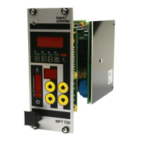
Detailed view and labeling of the MPT 700 front panel controls and indicators.
Explains the general operation and parameter entry procedures for the unit.
Details on operating mode 1, focusing on fixed pulse width heating.
Explains operating mode 2, covering heating/cooling with fixed pulse width.
Describes operating mode 3, involving variable pulse width and spacing for heating.
Covers operating mode 4, for heating/cooling with variable pulse width and spacing.
Details mode 5, for heating with fixed pulse width and separate air/gas valve control.
Explains mode 6, for heating/cooling with fixed pulse width and separate air/gas valve control.
Describes mode 7, for heating with variable pulse width/spacing and separate air/gas valve control.
Covers mode 8, for heating/cooling with variable pulse width/spacing and separate air/gas valve control.
Explains parameter 10, which defines the setting source for operation and faults.
Details parameter 11, which sets the operating mode of the unit.
Information on parameters 12 and 13 for setting the equipment address.
Describes parameter 14, which controls the setting indicator behavior.
Explains parameters 15 and 16 for configuring the number of outputs.
Details parameter 18, which selects the MPT operating mode (608 or 128).
Covers parameter 19, setting the keyboard repetition rate for editing values.
Explains parameters 20-27 for setting ignition timing for channels 1 to 8.
Details parameters 28 and 29 for setting the control factor.
Explains parameters 30 and 31 for setting the heating/cooling limit.
Covers parameters 32 and 33 for setting the heating/cooling dead zone.
Details parameters 34 and 35 for continuous pulse operation.
Explains parameters 36 and 37 for control rate with a three-point step controller.
Covers parameters 38 and 39 for fixed settings.
Details parameters for setting pulse widths for parameter sets 1 and 2.
Explains parameters for setting the minimum 'on' time.
Covers parameters for setting the minimum 'off' time.
Details parameters for setting delays in various modes.
Explains parameter 87 for setting the equipment code for parameter protection.
General installation guidelines and procedures for the MPT 700 unit.
Illustrates the connection plans for the MPT 700 unit's boards and components.
Provides a brief overview of the MPT 700's key settings and parameters.
Guides users through testing and servicing procedures for the MPT 700.
| Brand | krom schroeder |
|---|---|
| Model | MPT 700 |
| Category | Control Unit |
| Language | English |