MPT 700
10
2.1.5 Malfunction indicator
⇒ unit malfunction
• If the unit detects a malfunction during its cyclical self-test, the red LED is lit, the
4 green LEDs all flash and the binary "malfunction" output signal is activated.
Troubleshooting is described in section 5.4 below.
In case of the fault 'mA' is happened (source indicator 02), the green LED is lit
and the "malfunction" indicator is gone into steady light. Simultaneous the
output "malfunction" (Out /Error) is set.
2.1.6 Switching output indicators
• These LEDs indicate which outputs are being addressed at any time.
• As the indicators only indicate that the output drivers are being addressed, it is
not possible to use them for detecting a faulty output driver or a wire breakage.
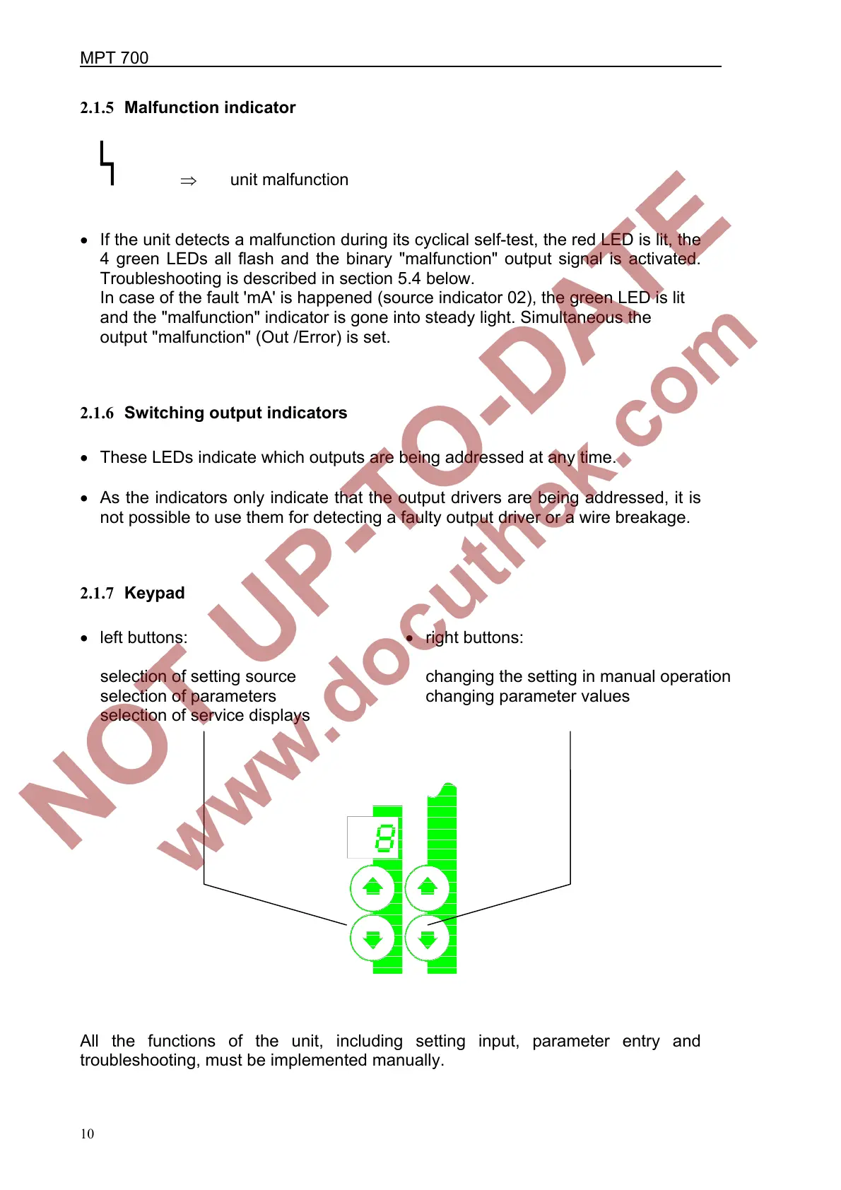
2.1.7 Keypad
• left buttons:
selection of setting source
selection of parameters
selection of service displays
• right buttons:
changing the setting in manual operation
changing parameter values
All the functions of the unit, including setting input, parameter entry and
troubleshooting, must be implemented manually.
 Loading...