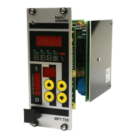
MPT 700
3
4.18 Parameters 50...53 / 56...59 / 70...73 / 76...79 - delays ................................ 39
4.19 Parameter 87 - equipment code.................................................................... 40
5 Appendix.......................................................................................... 41
5.1 Installation ........................................................................................................ 41
5.1.1 Proper use.................................................................................................. 41
5.1.2 Installation notes and safety precautions ................................................... 41
5.1.3 General ...................................................................................................... 42
5.1.4 Ground connection..................................................................................... 43
5.1.5 Power supply connections.......................................................................... 43
5.1.6 Binary control inputs................................................................................... 44
5.1.7 mA control inputs........................................................................................ 44
5.1.8 Switching outputs ....................................................................................... 45
5.2 Connection Plans ............................................................................................. 46
5.2.1 Main board ................................................................................................. 46
5.2.2 Power supply board.................................................................................... 47
5.2.3 Jumpers (on main board) ........................................................................... 48
5.2.4 Fuses (on power supply board).................................................................. 48
5.2.5 Block diagram (overview) ........................................................................... 49
5.2.6 Terminal plan (CN1) ................................................................................... 50
5.3 Brief instructions............................................................................................... 51
5.3.1 Modes of operation..................................................................................... 51
5.3.2 Parameter 10 - setting source .................................................................... 51
5.3.3 Parameters 0...99....................................................................................... 52
5.4 Test and service instructions............................................................................ 53
5.4.1 Parameter 5: test mA control input/phase .................................................. 54
5.4.2 Parameter 6: test of binary control inputs................................................... 54
5.4.3 Parameter 7: test of switching outputs ....................................................... 55
5.4.4 Parameter 8: error parameter number ....................................................... 55
5.4.5 Parameter 9: error code ............................................................................. 56
5.4.6 Parameters 90...98: event counters ........................................................... 57
5.4.7 Parameter 99: display test.......................................................................... 57
5.4.8 Cold start.................................................................................................... 57
5.4.9 Connections ............................................................................................... 57
5.5 Technical specifications ................................................................................... 58

 Loading...