IFD244, IFD258 · Edition 06.23
EN-3
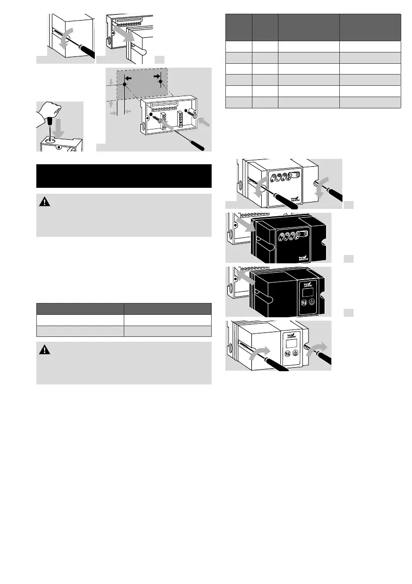
1
2
3
M16
4
70 mm
21 mm
∅
4 REPLACING THE AUTOMATIC
BURNER CONTROL UNIT IFS
CAUTION
– Dropping the device can cause permanent
damage. In this event, replace the entire device
and associated modules before use.
➔ Installation position as required.
➔ The housing dimensions and the hole pattern
have not changed.
➔ The new upper section of the housing will fit on
the existing lower section.
➔ The electrical connection is unchanged.
➔ Replacement possibilities:
Old unit New unit
IFS 244 IFD244
IFS 258 IFD258
CAUTION
– Only use the specified variants, when replacing
the automatic burner control units IFS244 or
IFS258.
Changes in comparison with the IFS:
➔ The IFD has a 7-segment display for indicating
flame signal intensity, operating state and flame
simulation.
➔ With the IFD, the fault signal occurs when mains
voltage is supplied.
➔ The IFD is additionally equipped with the follow-
ing protection functions:
➔ against over-frequent switching off during the
safety time on start-up, against over-frequent
remote resets and against over-frequent cycling.
The cycle lock is dependent on the safety time
on start-up and the ignition device.
t
SA
[s]
t
Z
[s] Type of
ignition
Cycle lock [s]
3 1.8 TZI 10
5 3 TZI 12
10 6 TZI 15
3 1.8 IFD..I 36
5 3 IFD..I 60
10 6 IFD..I 120
➔ In the event of a short-circuit on the valve output,
return the unit to the manufacturer.
➔ Max. number of operating cycles: 250,000.
➔ Mains voltage: IFD244: 120, 230V.
IFD258: 100, 120, 200, 230V.
1
IFS
2
3
4

 Loading...