IFD244, IFD258 · Edition 06.23
EN-4
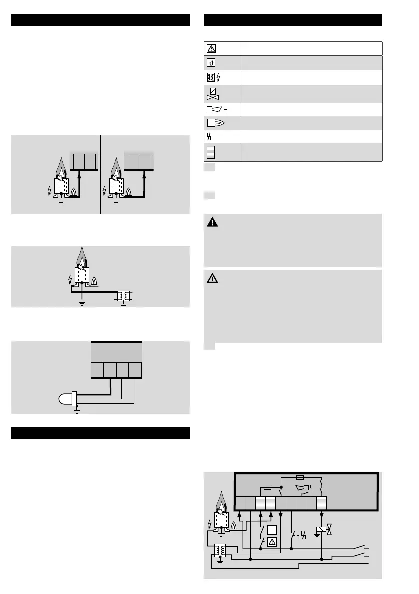
5 CABLE SELECTION
➔ Use mains cable suitable for the type of opera-
tion and complying with local regulations.
➔ Signal and control line: max. 2.5mm
2
.
➔ Cable for burner ground/PE wire: 4mm
2
.
➔ For the ionization and ignition cables, use un-
screened high-voltage cable:
FZLSi 1/7 up to 180°C, Order No. 04250410,
or
FZLK 1/7 up to 80°C, Order No. 04250409.
A = Ionization cable
➔ Max. 75m.
A
I
Z
5
A
I
Z
4
IFD 244 IFD 258
45
B = Ignition cable
➔ Max. 5m, recommended 1m.
➔ IFD..I: max. 1m, recommended 0.7m.
B
I
Z
IFD258
C = UV cable
➔ Max. 100m.
C
µA
5
UVS
1
2
3
6 74
6 CABLE INSTALLATION
Reduction of EMC
➔ External electrical interference must be avoided.
➔ Lay cables individually and, if possible, not in a
metal conduit.
➔ Do not lay UV/ionization cable and ignition cable
together and lay them as far apart as possible.
➔ Screw the ignition cable securely into the ignition
device and run to the burner by the shortest
possible route.
➔ Only use radio interference suppressed spark
plugs with a resistance of 1kΩ.
7 WIRING
Legend
Safety interlocks (limits)
Start-up signal
Ignition transformer
Gas valve
Fault signal
Operating signal
Reset
Safety circuit
1
Disconnect the system from the electrical power
supply.
➔ Use the pre-prepared knock-out holes for wiring.
2
Use M16 or PG11 plastic cable gland for 5 to
10mm cable diameter.
CAUTION
– Make a good PE (ground) wire connection to
the automatic burner control unit and burner,
otherwise the appliance may be damaged when
used in single-electrode operation.
WARNING
– Ensure that voltage outputs and inputs have the
same polarity and are not reversed.
– Connection only with permanent wiring.
– Do not reverse L1, N and PE.
– Do not set the reset function so that it operates
automatically in cycles.
3
Wire the automatic burner control unit as shown
in the connection diagram.
Connection diagrams
➔ The operation and fault signalling contacts do
not meet the requirements for safety extra-low
voltage (SELV/PELV).
A = Ionization control
B = Single-electrode operation
C = UV control
IFD244/IFD244..I
➔ Fault signalling contact (terminals 7/8): max. 2A,
253V, not fused internally.
L1
N
PE
1
2 3 4 5 6 7 8 9
I
Z
IFD 244
ϑ
max. 2 A,
253 V~
F1

 Loading...