IFD244, IFD258 · Edition 06.23
EN-5
L1
N
1
2 3 4 5 6 7 8 9
10 11 12 13 14
ϑ
max. 2 A,
253 V~
I
Z
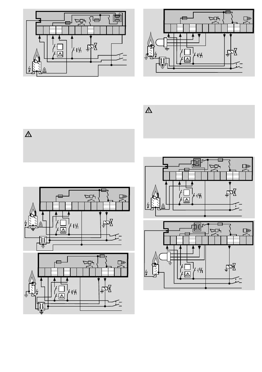
IFD 244..I
F1
IFD258
➔ Use the Elster Kromschröder ignition transformer
TZI/TGI in single-electrode operation B. Connect
burner ground to the IFD via terminal7, other-
wise the IFD will be damaged.
➔ Use the Elster Kromschröder UV sensor UVS for
UV control C.
WARNING
– For UV control, the IFD258 must be perma-
nently supplied with voltage. Do not switch on
the IFD power supply synchronously with the
heat demandϑ.
➔ Operation signalling contact (terminals 13/14)
and fault signalling contact (terminals 8/9):
max.2A, 253V, not fused internally.
➔ Terminals 11 and 12 are connected internally.
I
N (L2)
PE
1
2 3 4 5 6 7 8 9
10 11 12 13 14
ϑ
max.
2
A,
253
V~
max. 2 A,
253 V~
F1
N (L2)
PE
1
2 3 4 5 6 7 8 9
10 11 12 13 14
ϑ
max.
2
A,
253
V~
max. 2 A,
253 V~
Z
F1
L1 (L1)
N (L2)
PE
1
2 3 4 5 6 7 8 9
10 11 12 13 14
Z
1
2
3
UVS
ϑ
max.
2
A,
253
V~
max. 2 A,
253 V~
F1
IFD258..I
➔ Single-electrode operation is not possible.
➔ Use the Elster Kromschröder UV sensor UVS for
UV control C.
WARNING
– For UV control, the IFD258 must be perma-
nently supplied with voltage. Do not switch on
the IFD power supply synchronously with the
heat demandϑ.
➔ Operation signalling contact (terminals 13/14)
and fault signalling contact (terminals 8/9):
max.2A, 253V, not fused internally.
1
2 3 4 5 6 7 8 9
10 11 12 13 14
N (L2)
ϑ
max.
2
A,
253
V~
max. 2 A,
253 V~
I
Z
F1
1
2 3 4 5 6 7 8 9
10 11 12 13 14
IFD 258..I
L1 (L1)
N (L2)
PE
Z
1
2
3
UVS
ϑ
max.
2
A,
253
V~
max. 2 A,
253 V~
F1

 Loading...