IFD244, IFD258 · Edition 06.23
EN-2
2 CHECKING THE USAGE
IFD244/IFD258
For atmospheric burners or forced draught burners
used in multiple burner applications, where a central
control system is used for pre-purge and for mon-
itoring the limits. For direct ignition and monitoring
of gas burners in continuous operation. Suitable for
intermittent operation thanks to its fast reaction to
different process requirements. 2-digit 7-segment
display for indicating program status and flame
signal intensity.
IFD..I
With integrated ignition.
WARNING
– The user must ensure that the high-voltage
output (IFD..I) is protected against accidental
contact.
– The IFD..I may not be used for domestic,
commercial and trade, or small firm application
due to emitted electromagnetic interference.
IFD244
Gas burner monitoring with a flame rod. For ground-
ed mains. With restart after a flame failure.
IFD258
Gas burner monitoring with a flame rod or a UV
sensor.
In the case of UV control with UV sensors of Type
UVS, the IFD may be used for intermittent operation
only. This means that operation must be interrupted
once within 24hours.
Ionization control is possible in both grounded and
ungrounded systems.
Ignition and monitoring with a single electrode is
possible (single-electrode operation).
The cut-off point can be set using a potentiometer.
The behaviour in the event of flame failure during
operation can be selected using a switch. Either
an immediate fault lock-out or an automatic restart
occurs.
➔ Mains voltage, ambient temperature, safety
time, enclosure, and with IFD..I also the ignition
voltage (peak-peak) and ignition current– see
type label.
IFD
CE-0063BXXXXX
230 VAC
50/60 Hz
-20/+60 °C
-4/+140 °F
ts 5/1s
IP 54/NEMA 3
➔ No condensation permitted on the PC boards
(enclosure IP54).
➔ Length of sensor cable:
ionization control: max. 75m,
UV control: max. 100m.
➔ In the event of an automatic restart, the program
sequence started must match the application
and the burner must be able to restart as intend-
ed in all operating phases.
2.1 Type code
IFD Automatic burner control unit for contin-
uous operation
2 Series 200
4 Ionization control
5 Ionization or UV control
4 Restart in the event of flame failure
8 Immediate fault lock-out or restart,
switchable
-3 Safety time on start-up: 3s
-5 Safety time on start-up: 5s
-10 Safety time on start-up: 10s
/1 Safety time during operation: 1s
W Mains voltage: 230V AC, 50/60Hz
Q Mains voltage: 120V AC, 50/60Hz
Y Mains voltage: 200V AC, 50/60Hz
P Mains voltage: 100V AC, 50/60Hz
I Integrated electronic ignition
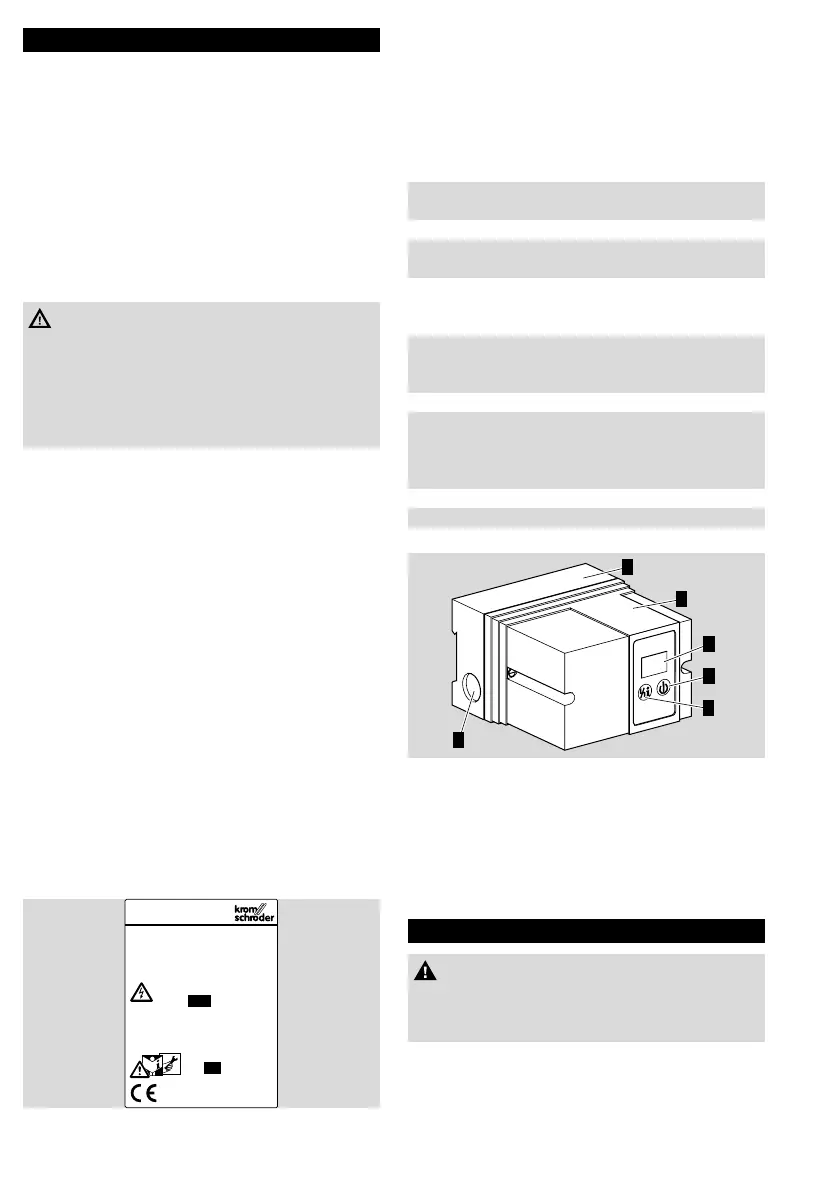
2.2 Part designations
2
6
3
1
4
5
1 LED display for program status and fault mes-
sages
2 On/Off button
3 Reset/Information button
4 Lower housing section
5 Upper housing section
6 Knock-out hole for M16 cable gland
3 INSTALLATION
CAUTION
– Dropping the device can cause permanent
damage. In this event, replace the entire device
and associated modules before use.
➔ Installation position as required.
➔ Eight knock-out holes are pre-prepared for
wiring, M16 plastic cable gland for 8 to 10mm
cable diameter.

 Loading...