20
Fan Powered Terminal Units IOM
HI
LO
RJ
MXF-544002-001
FLA
III V
1005-33-01
TABLE 13 – KLPP Parallel Fan Terminal Unit
UNIT SIZE INLET SIZE
PRIMARY AIR FLOW PCS MOTOR ECM MOTOR
MAX MIN MOTOR HP MAX FAN MIN FAN MOTOR HP MAX FAN MIN FAN
2
6 515 90
1/6 665 350 1/3 820 1658 920 160
10 1430 250
4
8 920 160
1/4 855 420 1/3 885 17510 1430 250
8X14 2060 360
TABLE 12 – QFV Parallel Fan Terminal Unit
UNIT SIZE INLET SIZE
PRIMARY AIR FLOW ECM MOTOR
MAX MIN MOTOR HP MAX FAN MIN FAN
2
6 515 90
1/10 400 200
8 920 160
3
8 920 160
1/10 600 300
10 1430 250
4
10 1430 250
1/4 1050 480
12 2060 360
5
12 2060 360
1/2 1500 860
14 2800 480
6
14 2800 480
1/2 1800 930
16 3660 630
7 16 3660 630 3/4 2200 1140
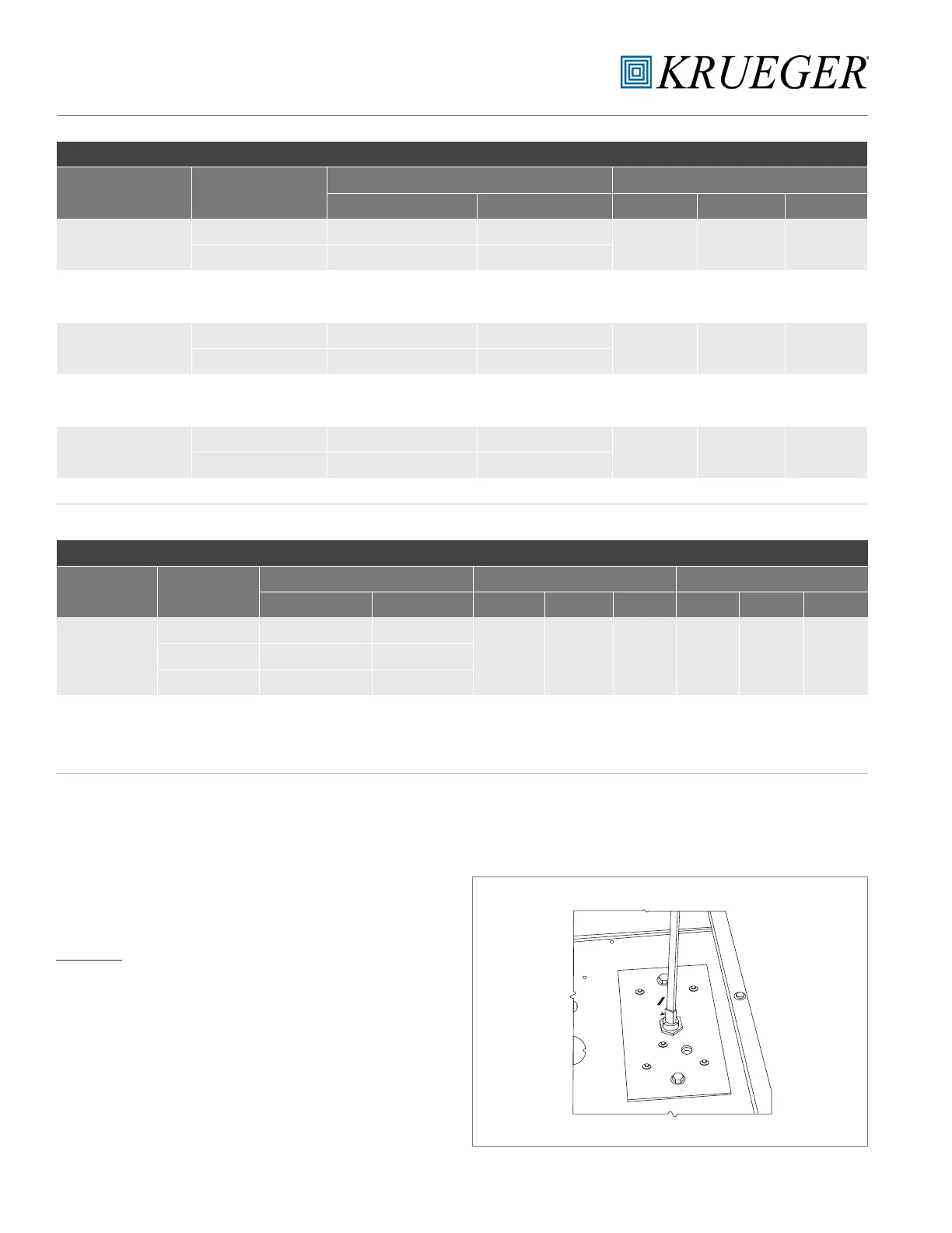
SPEED CONTROLLER
Each Krueger fan powered air terminal unit is equipped with
a fan SCR speed controller, located on the bottom of the
control box. The SCR can be adjusted in the eld. (The QFC,
size 7 unit has 2 SCR speed controllers, one for each fan. One
SCR is located in the standard position at the bottom of the
control box; the other is at the top of the control box.)
CAUTION: The minimum stop on the speed controller
is factory set at an internal minimum stop to prevent
damage to the motor. Do not attempt to override this
minimum stop or electrical damage to the fan motor
may result.
The fan airow output is dependent on the setting of the
controller and the downstream static resistance.
TO INCREASE THE FAN SPEED (RPM)
Turn the slotted adjustment on the controller clockwise
toward the “HI” marking printed on the controller faceplate.
(Refer to Figure 9.)
TO DECREASE THE FAN SPEED (RPM)
Turn the slotted adjustment on the controller clockwise
toward the “LO” marking. (Refer to Figure 9.)
FIGURE 9 – Fan Speed Controller
TABLE 12 – QFV Parallel Fan Terminal Unit
TABLE 13 – KLPP Parallel Fan Terminal Unit