21
Fan Powered Terminal Units IOM
SETTING FAN AIR FLOW WITH ECM MOTORS
Several terminal unit models are available with ECM motors
for easy balancing. These motors supply a determined
amount of air regardless of static pressure from ductwork
layout or air distribution. The ECM motors are programmed
to provide a maximum CFM depending on model and unit
size. The motors are then set to provide the desired CFM as
a proportional amount of the maximum. The proportion can
be set by several options:
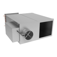
MANUAL SPEED CONTROL (CONTROL OPTION 6)
Manual speed controlled units are manually operated
with a digital readout on the ECM controller (see Figure
10). The digital readout provides a percent of maximum.
A fan adjustment knob is rotated until the desired percent
is displayed. After 20 seconds from nal adjustment, the
controller display will alternate between percent and motor
RPM’s. See Tables 14-28 for the percent required for desired
CFM.
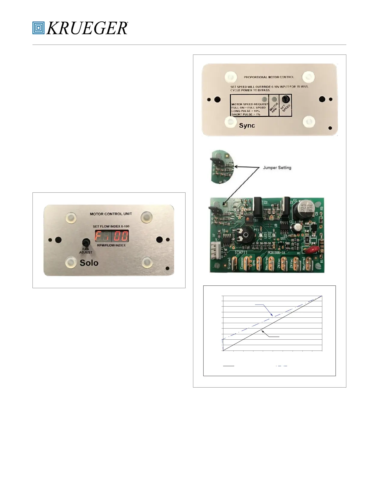
REMOTE SPEED CONTROL, 0-10Vdc (0-20mA) INPUT
(CONTROL OPTION 7)
The board is factory set to accept a 0-10Vdc signal to control
the airow between 0% and 100% as shown in the chart
in Figure 11. This option does not allow for on/o control.
Setting the jumper to the “Opt” position as shown in the
“Jumper Setting” in Figure 11 sets the control signal to
0-10Vdc signal.
REMOTE SPEED CONTROL, 2-10Vdc (4-20mA) INPUT
(CONTROL OPTION 8)
Another option is to have the board factory set to allow for
on/o control by setting the jumper on to the “P” position.
This setting uses a 2-10Vdc control signal range with a
voltage signal under 2Vdc turning the motor o. See gure
11 for graph of operating range.
Note: Both Remote Speed Control Options provide a
manual Override for eld setting the ECM motor without
being connected to a DDC controller. If a DDC controller
is connected, adjusting the manual override will lock out
the automation signal for 15 minutes.
FIGURE 10 –Manual Speed, ECM Controller
FIGURE 11 – Remote Speed, ECM Controller
“Opt” Jumper
“P” Jumper
Volts
Flow Index
0-10Vdc 2-10Vdc with On/O
10
9
8
7
6
5
4
3
2
1
0
0 10 20 30 40 50 60 70 80 90 100