Do you have a question about the KSB AMTRONIC R1300 and is the answer not in the manual?
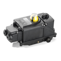
Overview of the AMTRONIC's suitability and general features for pneumatic actuators.
Detailed technical data including environmental, material, and operational parameters.
Step-by-step guide for fitting AMTRONIC to specific ACTAIR and DYNACTAIR actuator series.
Assembly instructions for larger capacity ACTAIR NG and DYNACTAIR NG pneumatic actuators.
Instructions for assembling AMTRONIC on heavy-duty ACTAIR and DYNACTAIR actuators with specific dimensions.
Exploded view and guidance for fitting the AMTRONIC unit to linear pneumatic actuators.
Details for direct and piped pneumatic connections, including pressure and exhaust ports.
Procedure for setting valve operating times using adjustment screws based on actuator type.
Information on IP67 plugs, cable glands, and accessing connection terminals.
Guide for connecting EV1 and EV2 solenoid valves based on distributor type.
Details on wiring position detection contacts and DPI detectors.
Wiring diagram for connecting an optional angle sensor to the AMTRONIC unit.
Overview of the optional feedback position sensing feature.
Overview of the optional heating resistance feature.
Safety position on loss of electrical supply for monostable distributor configurations.
Safety position on loss of electrical supply for bistable distributor configurations.
Safety position on loss of electrical supply for 4/3 distributor configurations.
Instructions on operating the solenoid valves manually using emergency controls.
Step-by-step guide to adjust the position of limit switch cams for proper detection.
Procedure for calibrating feedback position output by adjusting potentiometers.
| Brand | KSB |
|---|---|
| Model | AMTRONIC R1300 |
| Category | Control Unit |
| Language | English |