2
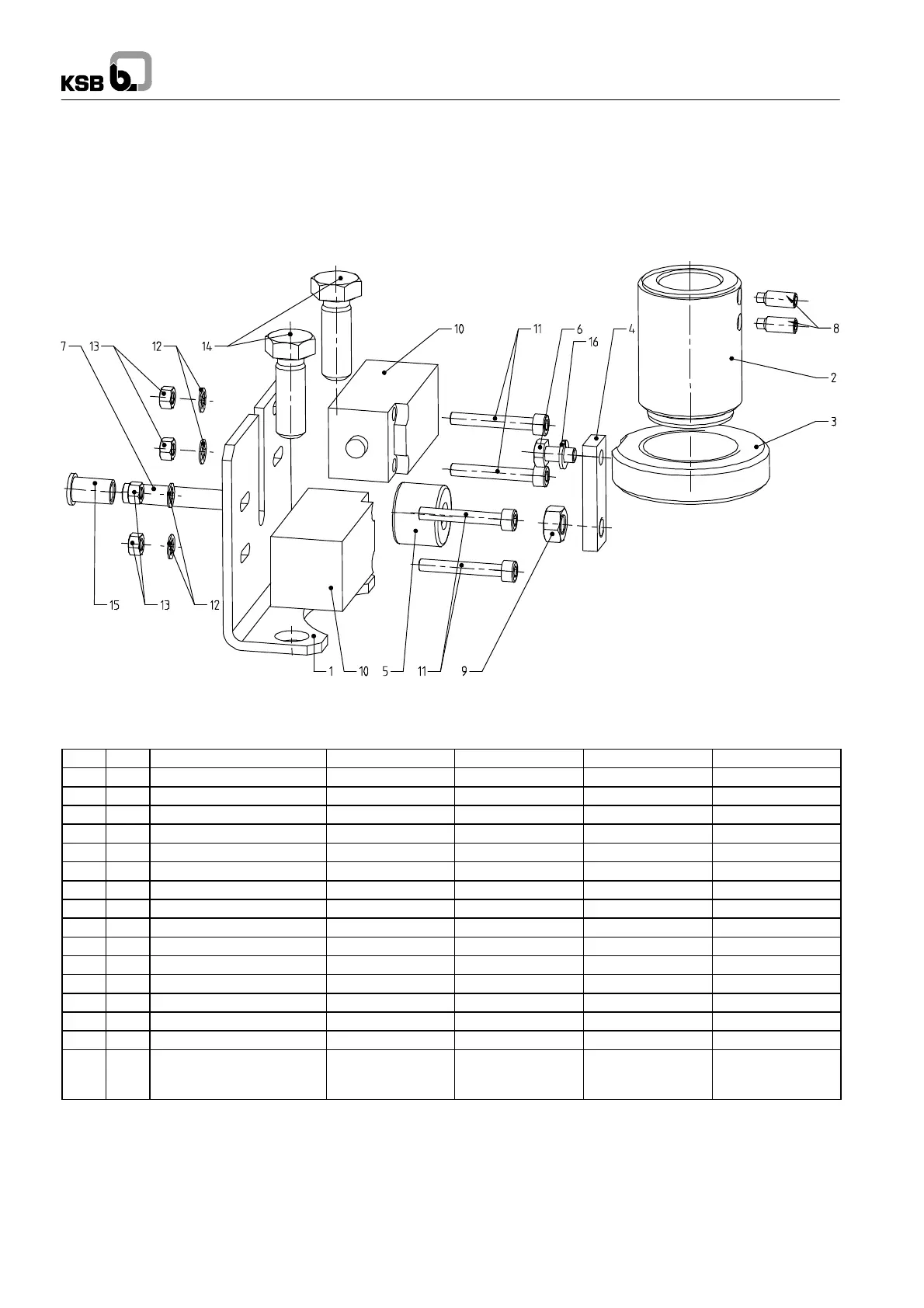
Fig. 1 Exploded view of limit switch set
The set includes one limit switch.
A second limit switch is available on request.
Please refer to Fig. 2 (example: DN 50, set 4) regarding
individual components.
Assembly instructions: s ee Fig. 3 to Fig. 9.
Fig. 2 Parts list f o r limit switch set (example: DN 50, set 4).
16 1 Spring washer A6 DIN 128 A4
15 1 Protective cap A7x16NT ZN 1252 01183921
14 2 Hexagon head bolt M12x35 ISO 4017 A2-70
13 4 Hexagon nut M5 ISO 4032 8+A2A
12 4 Serrated lockwasher J5.3 ISO 6798 FSTPHR
11 4 Socket head cap screw M5x35 ISO 4762 8.8
10 1 Limit switch XCK-P2110P16 UG1020001 as specified 46001831
9 1 Hexagon nut M8 ISO 4032 8+A2A 00182269
8 2 Grub screw M6x12 ISO 4026 A4-21H
7 1 Grub screw M8x55 ISO 4026 45H + A2A 01037673
6 1 Hexagon head bolt M6x12 ISO 4017 8.8 + A2A
5 1 Contact piece UG1297318 1.4021
4 1 Fixing plate UG1295815 1.4016
3 1 Switching nut UG1295756 1.4021
2 1 Threaded bush UG1295675 1.4021
1 1 Mounting bracket UG1295367 1.4016
Pos. Qty. Description Stock
Halbzeug
Stock
Drawing/Norm-No. Material Ident-No.
 Loading...