Caution
Caution
Caution
Caution
3
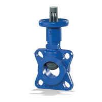
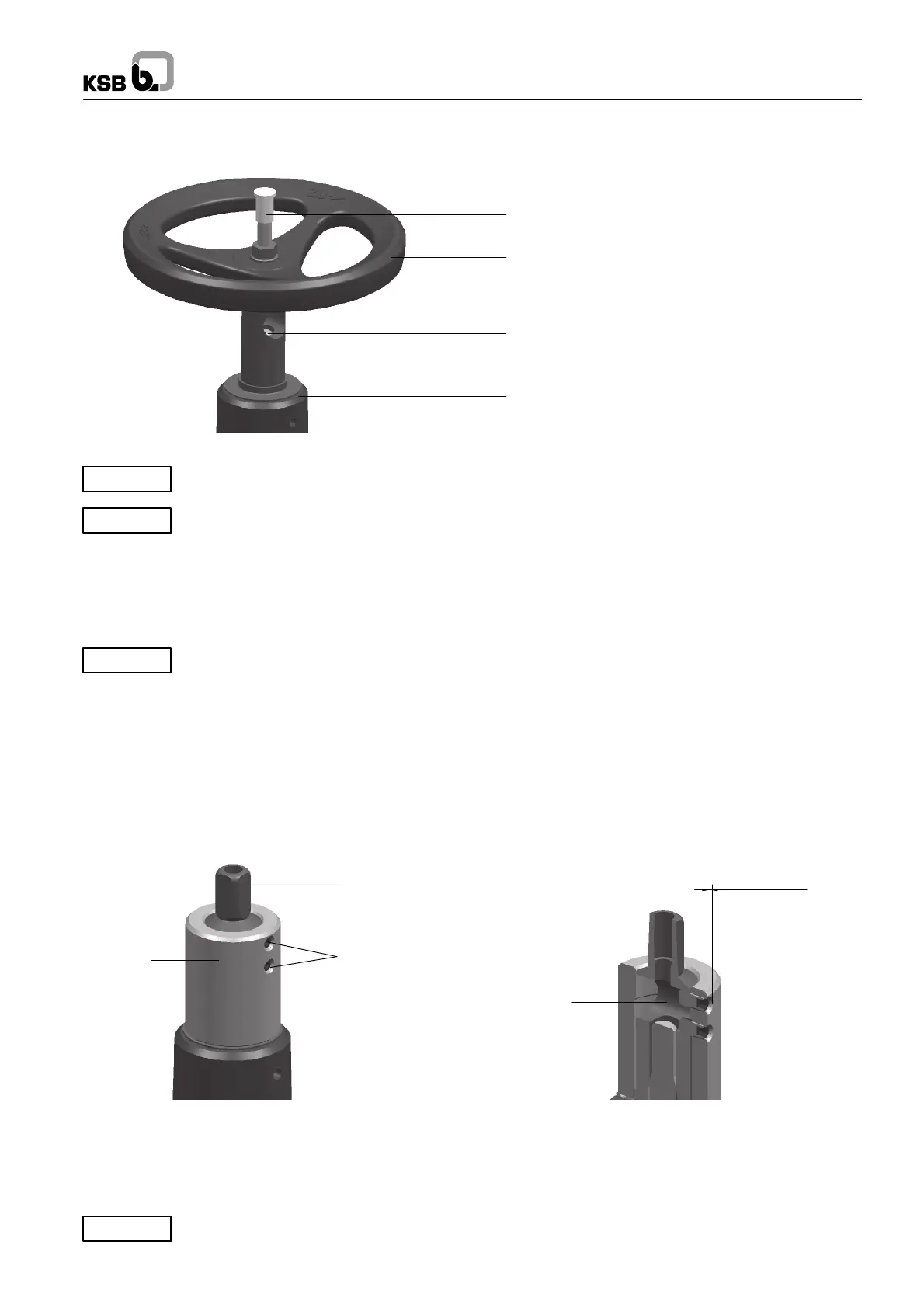
Fig. 3 Dismantling
Grub screw with hexagon nut and washer
Handwheel
Transverse hole in stem nut
Collar bush
First turn valve OPEN.
The valve cannot be operated during the modification work (because the handwheel must be removed).
Withvalveinsitu:
Prior to modification, valve pressure must be released and the valve must be allowed to cool down to below the fluid’s evaporation
temperature in all areas in contact with the fluid in order to effectively prevent any risk of scalding (see operating manual).
The c ollar bush must be removed with the valve OPEN.
Carefully lever off the collar bush (interference fit on stem nut).
CLOSE the valve.
The valve cannot be operated during the modification work (because the handwheel must be removed).
Dismantle the following parts:
-- Grub screw
-- Hexagon nut
-- Washer
-- Handwheel
-- Collar bush (no longer required)
Fig. 4 Fitting the threaded bush
Stem nut
Grub screw (8), 2 ea.
Transverse hole
approx. 2--3 mm
Threaded
bush
-- Push the threaded bush (2) onto the stem nut up to the stop.
-- Turn the threaded bush (2) such that the threaded holes align with the transverse hole (cf. Fig. 3).
-- Fit the threaded bush (2) on the stem nut with two grub screws (8) so that the grub screws extend into the transverse hole.
-- Turn the grub screws (8) in another approx. 2–3mm.
The s witching nut (3) must fit on top, as shown in Fig. 5.
 Loading...