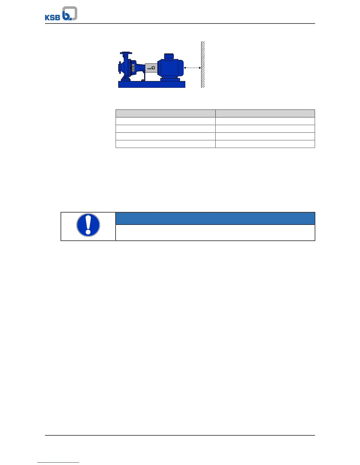
Fig.2: Minimum distanceX
Table8: Minimum distanceX to neighbouring assemblies
Motors with shaft centreline height [mm] Minimum distanceX [mm]
71 - 100 30
112 - 132 40
160 - 180 50
200 - 225 60
5.2 Installing the motor
Checks prior to installation work
▪ Repair any damage to the paintwork. (ðSection7.2.2.1,Page28)
▪ Remove any anti-corrosives applied to exposed metal parts that are required to
ensure proper assembly or installation.
Alignment and fastening
NOTE
Maintain the vibration levels to ISO 10816-1 during operation.
Observe the following when aligning and fastening:
▪ Ensure that the motor feet are resting evenly on the support surface.
▪ Ensure that feet and flanges are mounted as specified in the manual.
▪ Avoid rigid couplings.
▪ Ensure precise alignment for direct coupling.
▪ Ensure that mounting surfaces are free from contamination.
▪ Avoid resonances caused by the structure at the rotational frequency and double
mains frequency.
▪ Unusual noise that may occur when rotating the rotor by hand.
Compensation of radial
misalignment at the
coupling and horizontal
adjustment
The following measures are required to compensate radial misalignment at the
coupling and horizontally adjust the motor in relation to the driven machine (e.g. the
pump):
▪ Vertical positioning
To avoid distortion (warping) of the driven machine and the motor, place thin
metal sheets under the motor feet.
The number of shims should be restricted to a minimum, in other words, they
should only be stacked if this is unavoidable.
▪ Horizontal positioning
For horizontal positioning, laterally shift the motor on the foundation while
maintaining axial alignment (to prevent angular misalignment).
Ensure a uniform circumferential axial clearance at the coupling when
positioning.
▪ Smooth running characteristics
A stable, vibration-free foundation to DIN4024, exact alignment of the coupling
and a well-balanced output element (coupling, pulley, fan, etc.) are prerequisites
 Loading...