5 Installation at Site
19 of 36
KSB IE3-Motor
ð The terminal boards of motors with shaft centreline heights of 80mm and
90mm may differ from the schematic shown. In this case, star configuration
or delta configuration is selected by setting jumpers.
5. Optionally, the 2-core connection of the series-connected PTC thermistors for
temperature monitoring of the motor can be connected to terminals 1T1 and
1T2 with a suitable thermistor relay (PTC thermistor tripping unit). Observe the
maximum measuring voltage!
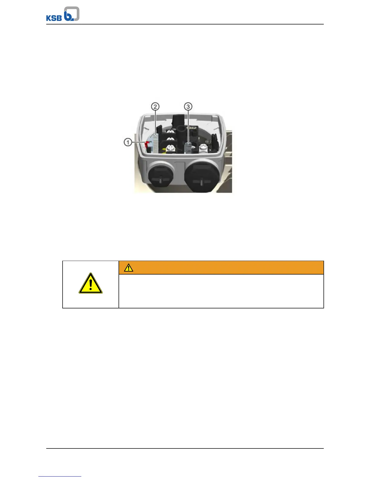
Changing the jumpers
Fig.5: Jumper position
1. Disengage the red locking lever (1) and pull the jumper (2) out of the slot.
2. Undo the snap hook at the storage pocket and take out the jumper (3).
3. Push the jumper (3) into the slot until it rests on the bottom. Engage the locking
lever again.
4. Place the jumper (2) into the storage pocket and engage the snap hook.
5.3.2 Checking the direction of rotation
WARNING
Parts flying off
Personal injury and damage to property!
▷ When checking the direction of rotation with the coupling removed, secure the
respective keys to protect them from being thrown off.
The motors are configured for clockwise and anti-clockwise rotation as standard.
Select the drive's direction of rotation to match the direction of rotation required by
the driven centrifugal pump.
Clockwise rotation
Connecting the power cables in the phase sequence U1, V1, W1 to L1, L2, L3 of the
power supply network results in clockwise rotation (looking at the drive shaft end).
Anti-clockwise rotation
Interchanging two connections, e.g. V1, U1, W1 to L1, L2, L3 results in anti-clockwise
rotation.
 Loading...