Operating data display
The device alternately displays the suction pressure and
discharge pressure as well as the differential pressure or head.
Recording and analysing of the load profile
The operating hours of the pump in the
different modes of operation are recorded in
a load profile and saved in a non-volatile
memory (protected against power failure).
The energy efficiency symbol is displayed
when a potential for optimisation is
recognised.
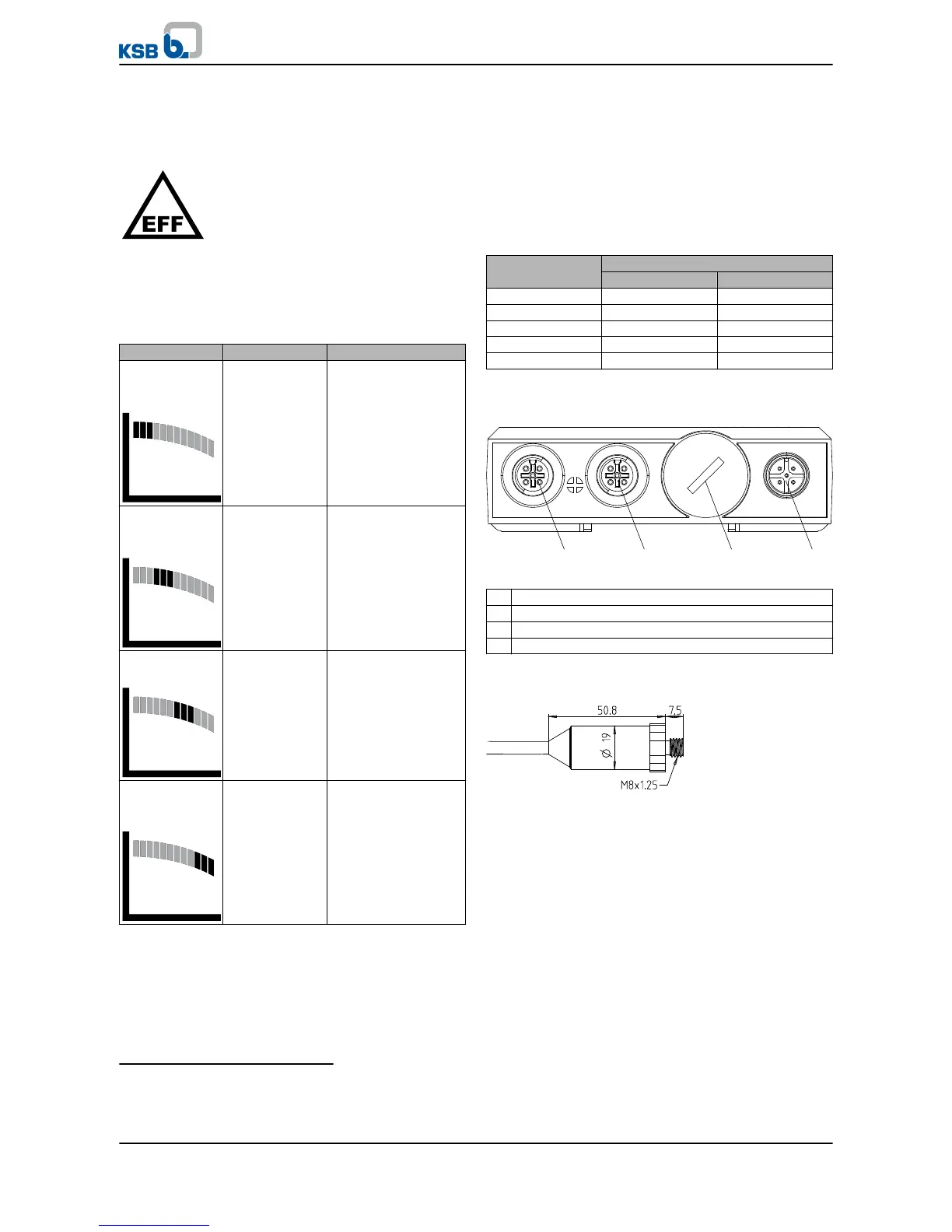
Qualitative indication of the pump's current operating point
The flashing segment indicates the position of the current
operating point on the generalised characteristic curve.
Qualitative indication of the pump's current operating point
Operating range Segment display Description
Operation at
extremely low
flow
3)
First quarter
flashing (1)
▪ Pump possibly not
operated in
accordance with its
intended use
▪ Increased load on
the components
Operation at
moderately low
flow
3)
Second quarter
flashing (2)
▪ Operation with
potential for
optimising energy
efficiency
Operation near
the optimum
Third quarter
flashing (3)
▪ Operation within
intended operating
range. Optimum
energy efficiency
Operation in
overload
conditions
Fourth quarter
flashing (4)
▪ Limit of the
intended operating
range
▪ Possibly overload
of pump and/or
motor
Design variants
▪ Adapter:
Depending on thread type and size of the pump's pressure
gauge connections
▪ Cable length:
600 mm or 1200 mm, depending on the pump size
▪ Measuring ranges of the pressure sensors:
Depending on the inlet pressure and maximum head
Available measuring ranges
Colour code Measuring range
Minimum Maximum
red -1 bar 3 bar
blue -1 bar 10 bar
light grey -1 bar 16 bar
green -1 bar 25 bar
black -1 bar 40 bar
Electrical connections
Connections at the device
1 IN1 / port for the suction-side pressure sensor
2 IN2 / port for the discharge-side pressure sensor
3 Service interface
4 EXT / external port for energy supply and signal output
Dimensions and weights
Dimensions of the sensor
3)
For some pump characteristics, no differentiation is made between the low-flow operating conditions in the curve's first
two quarters (both flashing simultaneously).
Monitoring
Intelligent Pressure Sensor
4
PumpMeter