Do you have a question about the KStar YDC9300-B and is the answer not in the manual?
Lists critical safety precautions for operating and handling the UPS equipment to prevent hazards and damage.
Explains warning symbols like "WARNING!" and "CAUTION!" used throughout the manual for safety guidance.
Provides a summary of the UPS capabilities, applications, and design, highlighting its online, high-frequency, three-in-single-out configuration.
Details the UPS's key functions including Digital Control, Battery Configurability, Intelligent Charging, LCD Display, and Monitoring capabilities.
Outlines the procedure for checking the UPS upon unpacking, including inspection for damage and verification of accessories.
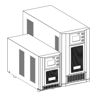
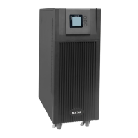
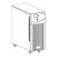
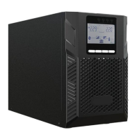
Presents the physical appearance of the UPS cabinets, including front, side, and rear views for different models (10-20k H/S).
Details the components and introduction to the UPS LCD control panel, including LED indicators, LCD display, and buttons.
Provides crucial installation notes regarding environment, temperature, humidity, and battery placement for optimal UPS performance and safety.
Explains the necessity and guidelines for installing external circuit breakers for AC supply and batteries to prevent over-current and ensure safety.
Details power cable design compliance, voltage/current considerations, and provides a table for recommended cable dimensions based on UPS cabinet size.
Provides step-by-step instructions for connecting power cables for single and dual input UPS versions, emphasizing isolation and safety precautions.
Explains the battery connection framework for standard and optional UPS models.
Explains the standard battery connection framework, including positive, negative, and neutral cables for the UPS, for 16-piece configurations.
Details the battery connection for optional models, including long-run units with varying battery quantities (18/20 or 32-40 pieces).
Guides on installing UPS units for parallel operation, including cabinet and cable setup.
Guides on connecting multiple UPS units for parallel operation, including input breaker status and battery group connection for system setup.
Explains the installation of parallel cables in a ring configuration for reliable control and high reliability between UPS units in a parallel system.
Lists requirements for parallel UPS systems to ensure equal utilization and compliance, such as same rating and common bypass source.
Details how to access the UPS via computer using a USB cable and the Muser4000 software for monitoring and control.
Guides on using Muser4000 software to set parameters, append equipment, and establish computer connection for UPS management and configuration.
Explains the various operating modes of the UPS, including Normal, Battery, Bypass, ECO, and Maintenance modes with schematic diagrams.
Details the procedures for turning the UPS on, off, and restarting it.
Provides a step-by-step procedure for restarting the UPS, emphasizing grounding and safety precautions before powering on.
Outlines the procedure for testing the UPS operation, including simulating utility failure and recovery, and using dummy loads for verification.
Explains how to activate the internal mechanical bypass switch to supply the load via Mains, noting load is unprotected in this mode.
Details the procedure for cold starting the UPS, especially when utility fails but the battery is normal, including power switch and button presses.
Provides detailed procedures for completely shutting down the UPS in both online and battery modes, emphasizing safety and discharge time.
Guides on connecting the UPS to a computer and using Muser4000 software to configure parallel settings like work mode, ID, and quantity.
Provides an overview of the UPS operating panel, including LED indicators, LCD display, and buttons, with a list of 12 interface descriptions.
Lists and describes the 12 interfaces available on the UPS LCD display, showing items like CODE, Input/Output Voltage, Load, and Temperature.
Illustrates various LCD display screens showing operational status, input/output parameters, battery status, and backup time.
Shows additional LCD display examples for Temperature, Software version, and Alarm Code, along with charging status indicators.
Explains how to access and adjust UPS parameters using the three control buttons, detailing the process for entering the setting menu.
Guides on setting the UPS operation mode (ECO, PAL, NOR) via the LCD panel, including saving settings and proceeding to voltage adjustment.
Details how to adjust the output voltage (220, 230, 240V) using the LCD panel, emphasizing the need to turn off the inverter first.
Explains how to set the UPS output frequency (50/60Hz) via the LCD panel, noting the prerequisite of turning off the inverter.
Guides on setting the battery capacity (1-999Ah) using the LCD panel, including quick adjustment methods and saving the values.
Details how to set the number of batteries connected to the UPS via the LCD panel, saving the quantity and moving to the next setting.
Explains how to set the upper limit for bypass voltage using the LCD panel, with available ranges specified for different output voltages.
Guides on setting the lower limit for bypass voltage via the LCD panel, specifying available ranges and saving the settings.
Details how to enable or disable the buzzer (MUTE ON/OFF) using the LCD panel, saving the mute setting state.
Explains how to configure periodical battery self-test options (OFF, ON 1, ON 2, ON 3) via the LCD panel for UPS maintenance.
Guides on enabling or disabling the battery temperature compensation sensor via the LCD panel and transferring to device address setting.
Details setting the device address (1-15) for MODBUS communication via RS232/RS485, including options for different configurations.
Guides on setting the parallel ID (1-4) for UPS units in parallel operation via the LCD panel, ensuring correct ID assignment.
Explains how to set the total parallel quantity of UPS units (2-4) via the LCD panel, saving the quantity and moving to the next setting.
Guides on setting the parallel redundancy quantity (0-3) via the LCD panel, saving the setting to complete UPS LCD panel configuration.
Lists operational status and mode messages displayed on the UPS, indicating Fault, Bypass, Battery, and Inverter states with LED indicators.
Provides a detailed list of alarm codes, corresponding UPS warnings, buzzer alerts, and LED indications for troubleshooting.
Details the optional SNMP card for remote monitoring and management of the UPS system via MEGAtec protocol.
Explains the optional Relay card's functions, including its 10-pin terminal for signals and dry contact outputs/inputs.
| Waveform | Pure Sinewave |
|---|---|
| Relative Humidity | 0-95% (Non-condensing) |
| Input Voltage | 220VAC |
| Output Voltage | 220VAC ± 3% |
| Frequency | 50Hz or 60Hz |
| Communication Interface | USB/RS232 |
| Operating Temperature | 0°C to 40°C |