
J
Jennifer TorresSep 8, 2025
What does 'Soft start fault' mean on KStar UPS?
- LLori ChristianSep 8, 2025
If your KStar UPS displays 'Soft start fault', it means that the rectifier could not be started due to low DC bus voltage.
What does 'Soft start fault' mean on KStar UPS?
If your KStar UPS displays 'Soft start fault', it means that the rectifier could not be started due to low DC bus voltage.
Why is my KStar YDC9300-RT UPS showing 'Mains freq. abnormal'?
If your KStar UPS displays 'Mains freq. abnormal', it means the mains frequency is out of the acceptable range, causing the rectifier to shut down.
What does 'DC Bus over-voltage' mean on my KStar YDC9300-RT UPS?
A 'DC Bus over-voltage' message on your KStar UPS indicates that the rectifier, inverter, and battery converter have been shut down due to a high DC bus voltage.
What does 'DC Bus under-voltage' mean on my KStar YDC9300-RT UPS?
A 'DC Bus under-voltage' message on your KStar UPS indicates that the rectifier, inverter, and battery converter have been shut down due to a low DC bus voltage.
What does 'Rectifier Over Temperature' mean on my KStar YDC9300-RT?
If your KStar UPS displays 'Rectifier Over Temperature', it means the temperature of the heatsink is too high to allow the rectifier to continue running. As a result, the charger and inverter will shut down.
What does 'Negative battery charger fault' mean on my KStar YDC9300-RT?
If your KStar UPS displays 'Negative battery charger fault', it indicates that the negative battery charger is faulty, and the charger will be shut down.
What does 'Battery charge thyristor failure' mean on my KStar UPS?
If your KStar UPS displays 'Battery charge thyristor failure', it signifies a failure of the battery charge thyristor.
What does 'Positive Battery Charger fault' mean on my KStar UPS?
If your KStar UPS displays 'Positive Battery Charger fault', it indicates that the positive battery charger is faulty, and the charger will be shut down.
What does 'DC bus unbalance' mean on my KStar YDC9300-RT?
If your KStar UPS displays 'DC bus unbalance', it indicates that the difference between the positive DC bus and the negative DC bus exceeds 30V.
What does 'Fan fault' mean on my KStar UPS?
If your KStar UPS displays 'Fan fault', it indicates that at least one of the cooling fans has failed. As a result, the rectifier, inverter, and charger will shut down.
General safety precautions for UPS installation and operation, including electrical shock and battery handling.
Explains warning and caution symbols used throughout the manual for safety awareness.
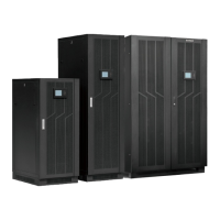
Overview of UPS capabilities, specifications, applications, and power problem solutions.
Lists key operational, design, modularity, and advanced features of the UPS system.
Steps for verifying UPS contents and checking for transportation damage before installation.
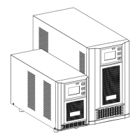
Illustrates the physical appearance and key features of the 1.4M 19" rack cabinet.
Details the physical appearance and specifications of the 2M 19" rack cabinet.
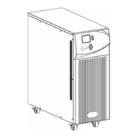
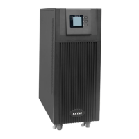
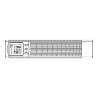
Shows front, rear, and side views of the UPS module with labeled components.
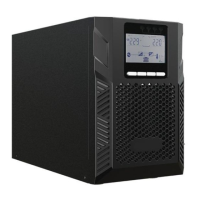
Introduces the controls and indicators on the UPS module's LCD panel for operation.
Crucial guidelines for UPS placement, environment, battery installation, and altitude considerations.
Requirements for external circuit breakers at AC input and battery connections for safety.
Guidance on selecting and installing power cables according to voltage, current ratings, and environmental conditions.
Step-by-step instructions for connecting power cables to the UPS terminals, including grounding.
Explains the positive/negative battery framework, series connection, and polarity requirements.
Procedures for inserting and removing UPS modules while the system is operating online.
Describes Normal, Battery, Bypass, and Redundancy operating modes of the UPS.
Covers starting, stopping, restarting, testing, and bypass operations for the UPS system.
Explains the main UPS LCD display interface, navigation keys, and information categories.
Details the LCD display interface and information presented for individual UPS modules.
Describes the control panel on top of the UPS for monitoring status, alarms, and basic operations.
Lists common UPS messages and their meanings for troubleshooting operational problems.
Discusses optional components like Network Management Cards and their features for remote monitoring.
Details electrical and physical specifications for various UPS cabinet capacities (20KVA to 100KVA).
Lists electrical, communication, environmental, and dimension specs for UPS modules.
Addresses common issues like display errors, power failures, LED indicators, and operational faults with recommended solutions.
Details the male port pinout, PC-UPS connection, and available RS232 functions for data exchange.
Specifies the baud rate, byte length, end bit, and parity check for RS232 communication protocol.