28
9)Select and confirm system setting menu,then:
System setting
10) Warning messages are shown as the pictures below.
no echo for setting error for setting switch delay
overload due to shutdown no output due to shutdown switch times
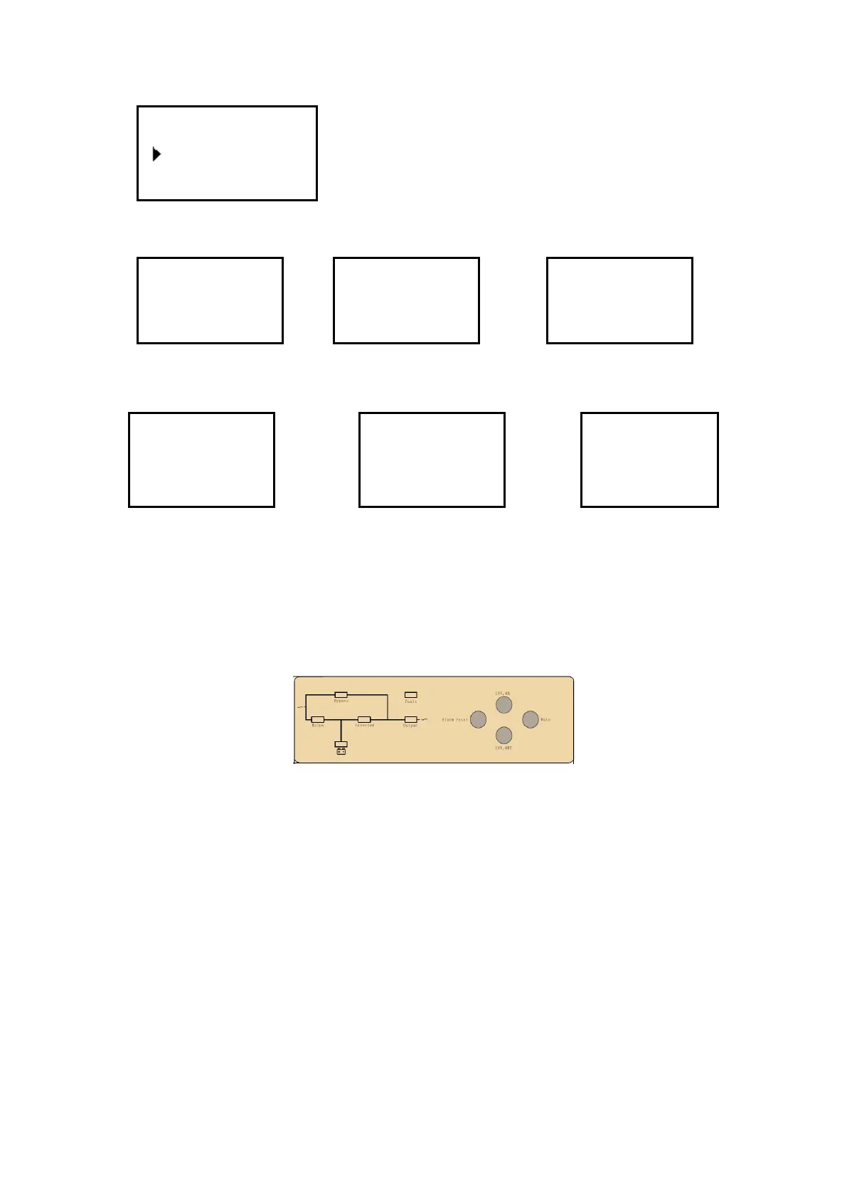
4.3.3 Monitoring module control panel
Monitoring module control panel is at UPS top. Through this control panel
and LED, the operator may monitor all measured datas, UPS & battery status,
and alarm events.
1) Power supply switch: the power supply switch of the monitoring module. After switch it off,
the monitoring module can be hot swapped.
2) EPO KEY: Disconnects Power to the Load. Disables rectifier, inverter, static bypass and
battery operation
3) MAINS INDICATOR (LED): the status of the AC Input
4) INVERT INDICATOR (LED): the status of the inverter
5) OUTPUT INDICATOR (LED): the status of the output
6) BYPASS INDICATOR (LED): the status of the bypass Input
7) BAT INDICATOR (LED): the status of the battery
8) FAULT INDICATOR (LED): UPS is faulty
9) ALARM RESET: to reset alarm.
10) MUTE: MUTE function of monitoring module, to mute buzzer, The buzzer will be
re-started automatically when fault occurs.
11) INVERTER OFF KEY: Disable Inverter Operation
Setting
Power Walk In On
Buzzer Stop
Warning!
Interrupt
switch prompt
Sure:Ent No:ESC
Warning!
Off will cause
sys.Overload
Sure:Ent No:ESC
Warning!
Off will cause
output failure
Sure:Ent No:ESC
Warning!
Switch Limited
Sure:Ent
 Loading...