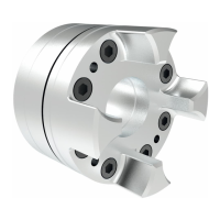
ROTEX
®
GS is a plug-in shaft coupling for measuring technology and automatic control engineering. It
is able to compensate for shaft misalignment, for example caused by manufacturing inaccuracies,
thermal expansion, etc.
1 Technical data 4
1.1 Types of hubs 4
1.2 Torques and finish bores 5
1.3 Coupling dimensions 6
2 Advice 17
2.1 General advice 17
2.2 Safety and advice symbols 18
2.3 General hazard warnings 18
2.4 Intended use 18
2.5 Coupling selection 19
2.6 Reference to EC Machinery Directive 2006/42/EC 19
3 Storage, transport and packaging 19
3.1 Storage 19
3.2 Transport and packaging 19
4 Assembly 20
4.1 Components of the coupling 20
4.2 Advice for assembly 23
4.3 Advice for finish bore 23
4.4 Assembly of the hubs (hub type 1.0, 1.1 and 1.2) 24
4.5 Assembly of the clamping hubs (hub types 2.0, 2.1, 2.5, 2.6, 2.8 and 2.9) 25
4.6 Assembly of clamping ring hubs (hub type 6.0 light, 6.0 steel and 6.0) 25
4.7 Disassembly of clamping ring hubs (hub type 6.0 light, 6.0 steel and 6.0) 27
4.8 Displacements - alignment of the couplings 27
5 Start-up 29
6 Breakdowns, causes and elimination 30
7 Disposal 32
8 Maintenance and service 33
9 Spares inventory, customer service addresses 33