Section 1: Assembly & Set-up
Table of Contents
11/13/19AP-SSG2524 Stump Grinder 328-215MK
10
Section 1: Assembly & Set-up
Skid Steer Requirements
The Stump Grinder is designed to attach to a universal
quick attach mounting system. Consult the skid steer
Operator’s Manual for operating capacity, lifting capacity,
and operating specifications. They will vary from unit to
unit. Do not exceed the rated capacities and
specifications of the skid steer.
WARNING
!
To avoid serious injury or death:
Lightweight power machines may need weight added to the
rear to maintain steering control and prevent forward tipping
or side tipping caused by a heavy front load. Consult your
power machine Operator’s Manual to determine proper
weight requirements and maximum weight limitations.
Torque Requirements
Refer to “Torque Values Chart” on page 37 to determine
correct torque values when tightening hardware.
Before You Start
Make sure that the intended skid steer conforms to the
requirements provided on this page. Also, read and
understand this Operator’s Manual for your Stump
Grinder. An understanding of how it works will aid in its
assembly and set-up.
The Stump Grinder is shipped fully assembled except for
the optional quick disconnect hose couplers and wire
harness. See “Section 4: Options” on page 20 for
detailed descriptions of options.
Go through the Set-up Checklist before preparing the
Stump Grinder for field use. To speed up your set-up task
and make the job safer, have all needed parts and
equipment readily at hand.
Set-up Checklist
Check Reference
Make sure all major components and
loose parts are shipped with the
attachment.
Assembly
& Set-up
Double check to make sure all parts,
fasteners, and pins are installed in the
correct location. Refer to the Parts
Manual if unsure.
NOTE: All assembled hardware from the
factory has been installed in the correct
location. Remember location of a part or
fastener if removed. Keep parts
separated.
Operator’s
Manual
328-215MK
Parts
Manual
328-215PK
Make sure working parts move freely,
bolts are tight & cotter pins are spread.
Operator’s
Manual
Make sure all grease fittings are in place
and lubricated.
Page 33
Make sure all safety labels are correctly
located and legible. Replace if damaged.
Page 6
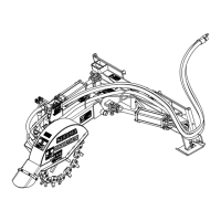
Customer Supplied Quick Couplers
Refer to Figure 1-1 on page 11:
4. Thread hydraulic hoses (#1, #2, & #12) through hose
loops (#5, #6, #7, & #8).
5. Consult your skid steer Operator’s Manual to
determine which hydraulic line on your attachment is
under pressure. Select customer supplied male (#4) or
female (#3) quick disconnect coupler that will mate
with your attachment’s pressure line coupling.
6. Screw selected coupler to line (#1) until tight.
7. Screw remaining coupler to line (#2) until tight.
8. Screw case drain coupler to line (#12) until tight.
9. If available, tie hydraulic hoses (#1, #2, & #12) together
with cable ties.
Skid Steer Hook-up
DANGER
!
To avoid serious injury or death:
A crushing hazard exists while hooking-up and unhooking the
attachment. Do not allow anyone to stand between attachment
and power machine while approaching or backing away from
the attachment. Do not operate lift and/or tilt controls while
someone is near the power machine and/or attachment.
WARNING
!
To avoid serious injury or death:
Check hitch fit-up frequently. An improper fit-up can cause the
attachment to come loose from the loader hitch plate and fall.
NOTE: Quick disconnect couplers (#3, #4, & #13)
are not included with the base unit. Optional
hydraulic quick couplers are available. See “Flat
Face Couplers” and “CTL/SS Coupler” on page 30
for detailed information and part numbers.
Refer to Figure 1-1 & Figure 1-4 on page 12:
How to identify hydraulic lines (#1, #2, & #12)
• Pressure Line (#1) connects to motor (#9)
• Return line (#2) connects to solenoids (#10 & #11).
• Case drain line (#12) connects to motor (#9).
NOTE: The Stump Grinder is designed for skid
steers with universal quick attach mounting system.
 Loading...