Section 1: Assembly & Set-up
Table of Contents
11/13/19AP-SSG2524 Stump Grinder 328-215MK
12
Hooking-up to the Stump Grinder
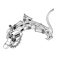
Figure 1-3
Refer to Figure 1-3:
1. Clean quick disconnect couplers(#3 & #4) of dirt and
connect male and female couplers to the skid steer
outlets. Make sure quick disconnect couplers have
fully engaged. If they have not, check the following:
a. Make sure couplers are same size and type.
b. Make sure hydraulic pressure has been released.
2. Clean case drain coupler (#13) and connect to skid
steer case drain coupler.
Hydraulic Hose Identification
Figure 1-4
Refer to Figure 1-4:
3. At a low engine rpm, engage hydraulics while
watching rotation of cutting wheel (#16).
• The cutting wheel should rotate counterclockwise
if looking at the cutting wheel from the motor (#9)
side as shown in Figure 1-4.
4. If cutting wheel rotates in the wrong direction, switch
male and female couplers on the hydraulic hoses and
then reconnect hoses to the skid steer outlets.
5. For additional help, refer to Hydraulic Hook-up in
your skid steer Operator’s Manual.
6. Continue with “Solenoid Hook-up” before operating
hydraulic cylinders.
35331
Return Line (#2) Connects To
Solenoids
Pressure Line (#1) Connects To
Hydraulic Motor
35332
Return Line (#2) Connects To
Solenoids (#10 & #11)
Pressure Line (#1) Connects To
Hydraulic Motor (#9)
Case Drain Line (#12)
Connects To
Hydraulic Motor (#9)
Solenoid Hook-up
There are five optional wiring harnesses available and
they all connect the same way to the Stump Grinder
solenoids. See pages 20-25 for a detailed description
and installation instructions of all five.
Refer to Figure 1-5 on page 13:
1. Thread wiring harness (#16) through hose support
loops (#5, #6, #7, & #8) as shown in Figure 1-1 on
page 11.
2. Locate solenoid (#11). It operates tilt cylinder (#17)
(controls up/down movement). Attach green wire
connector (#15) and red wire connector (#14) to that
solenoid.
3. Locate solenoid (#10). It operates the articulate
cylinder (controls left/right swing movement). Attach
brown wire connector (#13) and white wire
connector (#12) to that solenoid.
4. Attach solenoid wiring harness to the skid steer:
• If attaching one of the optional Deutsch HGD30
14 pin 2 functions harness, attach the internal
14 pin plug to the skid steer’s external 14 pin plug.
• If attaching optional toggle switch control harness,
see “Control Harness With Deutsch 2 Pin Plug”
on page 21
• If attaching optional toggle switch control harness
for Kubota CTL, see “Control Harness With 2
Eyelets” on page 25
5. While sitting in the skid steer seat with seat belt
fastened, start skid steer, turn auxiliary hydraulics
“on”, and extend tilt cylinder (#17).
6. If tilt cylinder operates in the opposite direction
desired, lower skid steer loader arms fully down and
change green wire connector with red wire connector
at the solenoid.
7. Return to the skid steer seat, raise Stump Grinder off
the ground, and extend articulate cylinder (#2)
shown in Figure 3-1 on page 17.
8. If articulate cylinder operates in the opposite
direction desired, lower skid steer loader arms fully
down and change brown wire connector with white
wire connector at the solenoid.
9. Continue with “Check Equipment Clearances” on
page 13.
 Loading...