1-S7
B7800HSD (SUPPLEMENT), WSM
HYDRAULIC SYSTEM
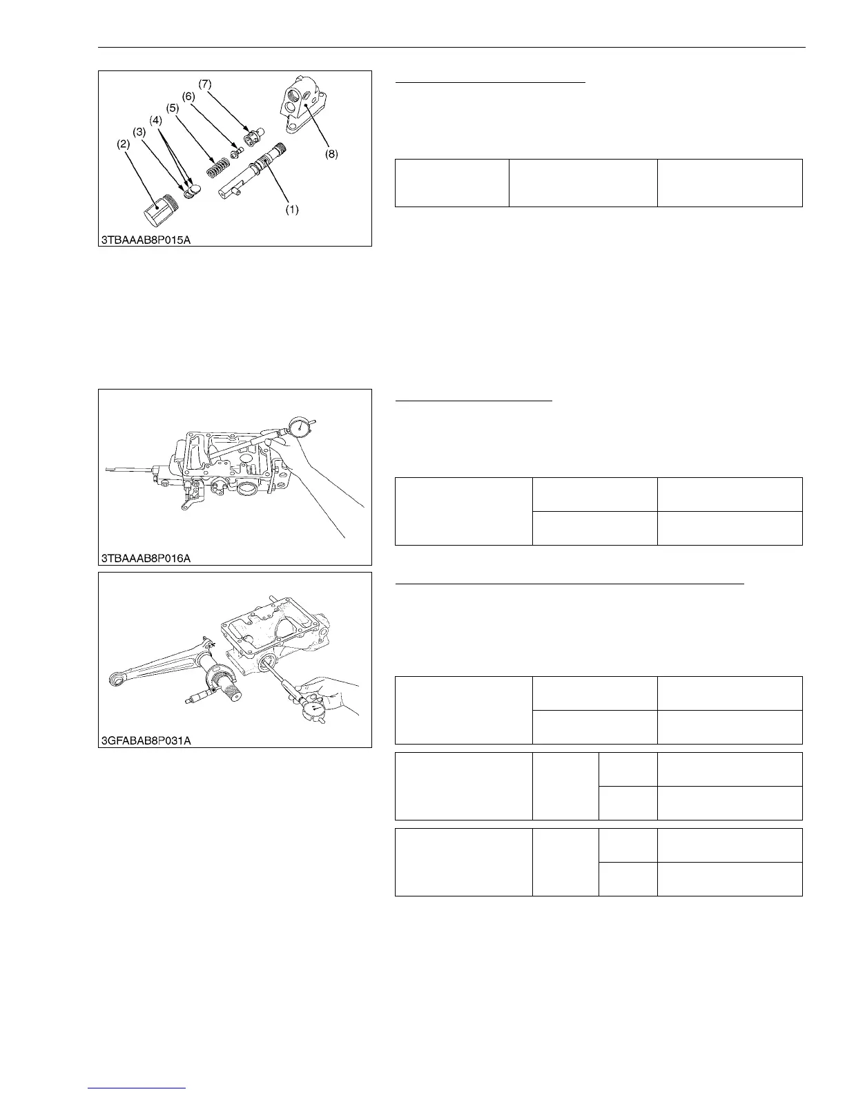
Disassembling Control Valve
1. Remove the spool (1).
2. Remove the plug (2) and draw out the washer (3), shims (4),
spring (5), poppet (6) and valve seat (7).
(When reassembling)
IMPORTANTQ
• After disassembling and assembling the relief valve, be sure
to adjust the relief valve setting pressure.
W1015713
[3] SERVICING
Hydraulic Cylinder Bore
1. Check the cylinder internal surface for spring or damage.
2. Measure the cylinder I.D. with a cylinder gauge.
3. If the measurement exceeds the allowable limit, replace the
hydraulic cylinder block.
W1016033
Clearance between Hydraulic Arm Shaft and Bushing
1. Measure the hydraulic arm shaft O.D. with an outside
micrometer.
2. Measure the bushing I.D. with a cylinder gauge, and calculate the
clearance.
3. If the clearance exceeds the allowable limit, replace the bushing.
W1016134
Tightening torque Relief valve plug
49.0 to 68.6 N·m
5.0 to 7.0 kgf·m
36.2 to 50.6 ft-lbs
(1) Spool
(2) Relief Valve Plug
(3) Washer
(4) Adjusting Shim
(5) Spring
(6) Poppet
(7) Valve Seat
(8) Control Valve Seat
Cylinder I.D.
Factory spec.
70.05 to 70.10 mm
2.7579 to 2.7598 in.
Allowable limit
70.15 mm
2.7618 in.
Clearance between
hydraulic arm shaft and
bushing
Factory spec.
0.020 to 0.110 mm
0.0008 to 0.0043 in.
Allowable limit
0.30 mm
0.0118 in.
Hydraulic arm shaft O.D.
Factory
spec.
Right
37.925 to 37.950 mm
1.4931 to 1.4941 in.
Left
33.925 to 33.950 mm
1.3356 to 1.3366 in.
Bushing I.D.
(after press fitted)
Factory
spec.
Right
37.970 to 38.035 mm
1.4949 to 1.4974 in.
Left
33.970 to 34.035 mm
1.3374 to 1.3400 in.
 Loading...


