8-M9
BX24, RCK54(P)-23BX, RCK60B-23BX, LA240, BT601, WSM
FRONT LOADER
Dump 2
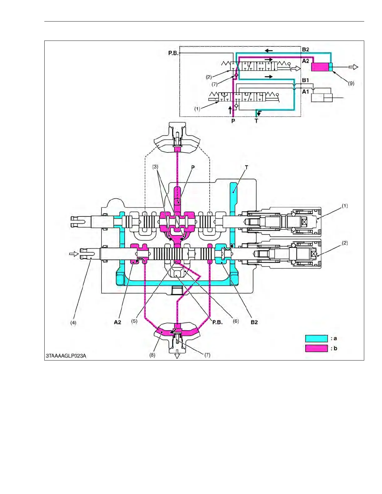
1. When the hydraulic control lever is set to the “DUMP 2” position, the spool (4) of the bucket control section (2)
moves to the right of the bucket control section (2) moves further to the right from the “DUMP 1” position, which
forms oil passages between passage 2 (8) and A2 port, and between B2 port and T port.
2. The pressure-fed oil from the P port flows to the neutral passage 2 (5) through the boom control section (1) and
P.B. passage 1 (3). As the oil passage from the neutral passage 2 (5) to the P.B. passage 2 (6) is closed by the
spool (4), this oil opens the load check valve (7) and flows through the notched section of the spool (4) and B2 port
to extend the bucket cylinder (9).
3. Return oil from the bucket cylinder (9) flows to the transmission case through the B2 port and T port.
(1) Boom Control Section
(2) Bucket Control Section
(3) P.B . Passage 1
(4) Spool
(5) Neutral Passage 2
(6) P. B. Passage 2
(7) Load Check Valve
(8) Passage 2
(9) Bucket Cylinder
P : P Port (From Pump)
T : T Port (To Tank)
P.B. :P.B. Port (To 3 Hitch)
A2 : A2 Port
(To Bucket Cylinder)
B2 : B2 Port
(From Bucket Cylinder)
a : Low Pressure
b : High Pressure

 Loading...