5.5
ELECTRICAL
SYSTEM
68
mm STROKE
SERIES
WSM,
01
161
DlSASS
EM
B
LIN
G
AND ASS
EM
B
LI N
G
[I]
STARTER
Disassembling Starter
I
B083F147
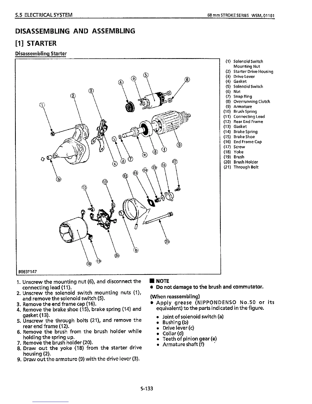
1. Unscrew the mounting nut
(6),
and disconnect the
NOTE
connecting lead
(1
1).
and remove
the
solenoid switch (5).
gasket
(1
3).
rear end frame
(1
2).
holding the spring up.
housing
(2).
2.
Unscrew the solenoid switch mounting nuts
(l),
3.
Remove the end frame cap
(1
6).
4.
Remove
the
brake shoe (15), brake spring
(14)
and
5.
Unscrew the through bolts
(21),
and remove
the
6.
Remove the brush from the brush holder while
7.
Remove the brush holder
(20).
8.
Draw out the yoke
(18)
from the starter drive
9.
Draw out thc armaturc
(9)
with the drivc lover
(3).
(1) Solenoid Switch
(2) Starter Drive Housing
(3)
Drive Lever
(4)
Gasket
(5)
Solenoid Switch
(6)
Nut
(7)
SnapRing
(8)
Overrunning Clutch
(9)
Armature
(IO)
Brush Spring
(1
1)
Connecting Lead
(12) Rear End Frame
(13) Gasket
(14) Brakespring
(15) BrakeShoe
(16)
End Frame
Cap
(17)
Screw
(18) Yoke
(19)
Brush
(20) Brush Holder
(21) Through Bolt
Mounting Nut
a
Do
not damage to
the
brush
and commutator.
(When reassembling)
a
Apply grease (NIPPONDENSO No.50 or
its
equivalent) to the parts indicated
in
the
figure.
0
Joint of solenoid switch (a)
0
Bushing(b)
0
Drive lever
(c)
0
Collar(d)
0
Teeth of pinion gear (e)
0
Armature
shaft
(9
’
S-133