M.l
ENGINE
BODY
68
mm STROKE SERIES
WSM,
01
160
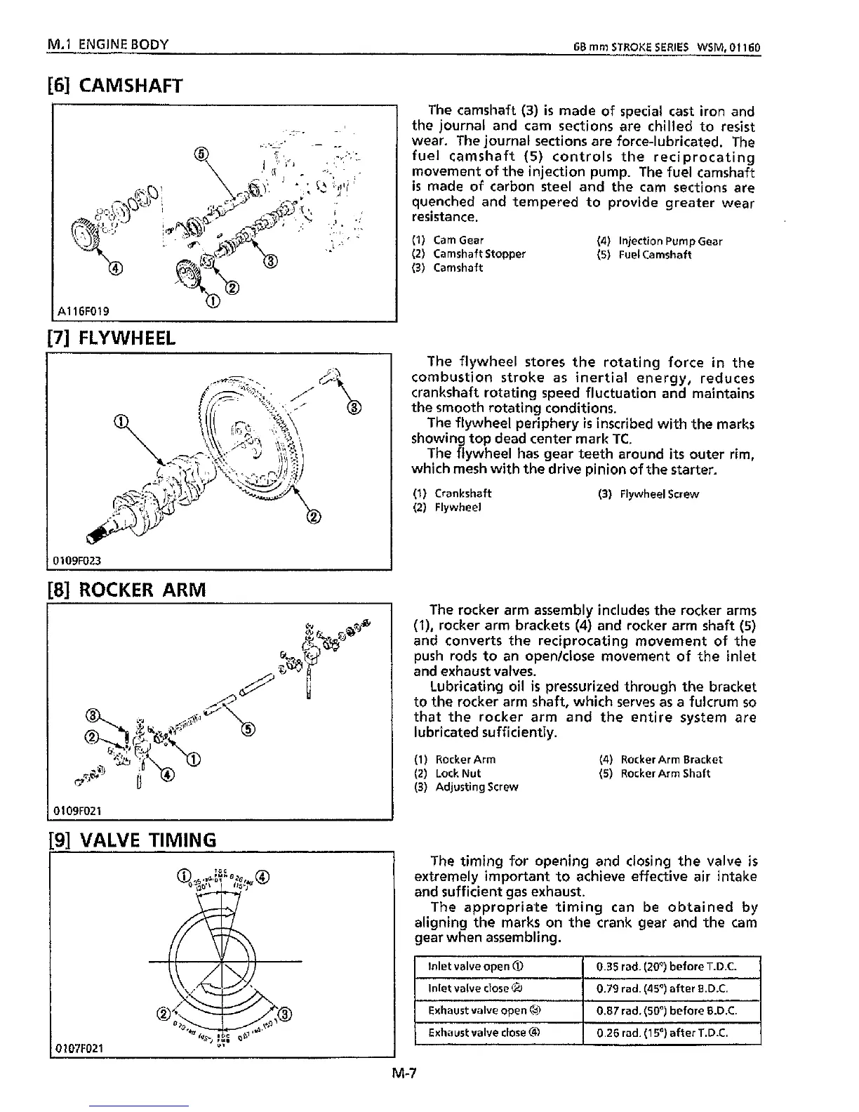
Inlet valve open
@
inlet valve close
6
[6]
CAMSHAFT
0.35
rad. (20') before T.D.C.
0.79 rad.
(45')
after B.D.C.
[7]
FLYWHEEL
Exhaust valve open
Exhaust valve close
@
The camshaft
(3)
is
made of special cast iron and
the journal and cam sections are chilled to resist
wear. The journal sections are force-lubricated. The
fuel camshaft
(5)
controls
the
reciprocating
movement of the injection pump.
The
fuel camshaft
is
made of carbon steel and the cam sections are
quenched and tempered to provide greater wear
resistance.
(1)
CamGear
(2)
Camshaft Stopper
(5)
Fuel Camshaft
(3)
Camshaft
(4)
Injection Pump Gear
0.87
rad.
(50')
before B.D.C.
0.26
rad.
(1
5")
after T.D.C.
The flywheel stores the rotating force in the
combustion stroke
as
inertial energy, reduces
crankshaft rotating speed fluctuation and maintains
the
smooth rotating conditions.
The flywheel periphery
is
inscribed with the marks
showing top dead center mark
TC.
The
flywheel has gear teeth around
its
outer rim,
which mesh with the drive pinion of
the
starter.
(1)
Crankshaft
(3)
Flywheel Screw
(2) Flywheel
01
09F023
81
ROCKER ARM
The rocker arm assembly includes the rocker arms
(l),
rocker arm brackets
(4)
and rocker arm shaft
(5)
and converts the reciprocating movement of the
push rods to an openklose movement
of
the inlet
and exhaust valves.
Lubricating oil
is
pressurized through
the
bracket
to the rocker arm shaft, which serves as a fulcrum
so
that
the
rocker arm and
the
entire
system are
lubricated sufficiently.
(1)
Rocker Arm
(4)
Rocker Arm Bracket
(2)
LockNut
(5)
Rocker Arm Shaft
(3)
Adjusting Screw
0109F021
[9]
VALVE
TIMING
I
I
0107F021
M-7